Condensation module and cooling tower
A condensing sheet and width technology, applied in the field of condensing modules, can solve problems such as environmental adverse effects, rain and snow falling, freezing damage, etc., and achieve the effect of improving heat exchange efficiency
- Summary
- Abstract
- Description
- Claims
- Application Information
AI Technical Summary
Problems solved by technology
Method used
Image

Examples
no. 1 approach
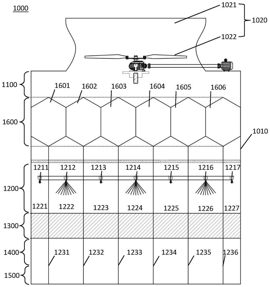
[0051] figure 1 It is a block diagram of the cooling tower of 1st Embodiment of this invention. Such as figure 1 As shown, in the body 1010 of the cooling tower 1000, an air mixing part 1100, a condensation part 1600, a spray part 1200, a heat exchange part 1300, an air introduction part 1400 and a water collection part 1500 are arranged from top to bottom. An exhaust part 1020 is provided on the upper part of the main body 1010, and the exhaust part 1020 includes an air duct 1021 and an induced draft fan 1022 disposed in the air duct 1021.
[0052] According to the above cooling tower, multiple sets of spray heads 1211 - 1217 on the upper part of the shower part 1200 spray hot water from the bottom to the bottom, and the hot water falls in the inner space of the shower part 1200 and enters the heat exchange part 1300 . In the heat exchange part, the hot water exchanges heat with the cold air flowing in from the lower part of the heat exchange part 1300, flows out from the l...
no. 2 approach
[0080] The difference between this embodiment and the first embodiment is that, in the condensation module 2600 of this embodiment, the first condensation sheet A and the second condensation sheet B are both formed in a rectangular shape.
[0081] Specifically, as Figure 9 As shown, the first introduction part 2610 is formed on the left side of the bottom of the condensation module 2600 in the width direction, and the second introduction part 2620 is formed on the right side of the width direction of the bottom of the condensation module 2600 . The first introduction part 2610 and the second introduction part 2620 are formed at the same height position. The first lead-out part 2640 is formed on the right side of the width direction of the top of the condensation module 2600 , and the second lead-out part 2650 is formed on the left side of the width direction of the top of the condensation module 2600 . The first lead-out part 2640 and the second lead-out part 2650 are formed...
no. 3 approach
[0084] Such as Figure 11 As shown, this embodiment is further improved on the basis of the cooling tower in the first embodiment. In the cooling tower of this embodiment, a cold air introduction part 3700 is provided on the lower side of the condensation module 1600 , and the cold air introduction part 3700 communicates with the first flow path in the condensation module 1600 . The cold air introduction portion 3700 extends horizontally through at least one side wall of the cooling tower 3000 to communicate with the outside air. Therefore, the dry cold air of the external air can flow into the first flow path of the condensation module 1600 through the cold air introduction part 3700 (such as Figure 11 indicated by the hollow arrow).
[0085] In addition, the air flowing in from the air introduction part 1400 passes through the heat exchange part 1300 and the shower part 1200 from bottom to top to become hot and humid air, and the hot and humid air continues to flow upward...
PUM
 Abstract
Description
Claims
Application Information
 - R&D
- Intellectual Property
- Life Sciences
- Materials
- Tech Scout
- Unparalleled Data Quality
- Higher Quality Content
- 60% Fewer Hallucinations
Browse by: Latest US Patents, China's latest patents, Technical Efficacy Thesaurus, Application Domain, Technology Topic, Popular Technical Reports.
© 2025 PatSnap. All rights reserved.Legal|Privacy policy|Modern Slavery Act Transparency Statement|Sitemap|About US| Contact US: help@patsnap.com