Concrete rebound test auxiliary device for surveying and mapping engineering

An auxiliary device and concrete technology, applied in the field of surveying and mapping engineering, can solve the problems of time-consuming and laborious, poor measurement accuracy, and achieve the effect of accurate position and guaranteed accuracy

Inactive Publication Date: 2020-11-06
付磊
0 Cites 0 Cited by

AI-Extracted Technical Summary

Problems solved by technology

[0004] The object of the present invention is to provide a concrete rebound test auxiliary device for surveying and mapping engineering, ...

Method used

As a preferred solution, further, the booster mechanism 5 includes a positioning cylinder 51, a slideway 52, a slide block 53, a spring 54 and a booster sleeve 55, and the positioning cylinder 51 is detachably arranged on the front side of the base plate 4, and The inner wall of the positioning cylinder 51 is provided with a slideway 52 along the circumferential direction. Through the cooperation of the slideway 52 and the slider 53, the booster sleeve 55 is limited to prevent the booster sleeve 55 from detaching from the positioning cylinder 51. The slider 53 and the spring 54 are arranged from front to back. Plugged into the inner cavity of the slideway 52, the spring 54 is a rotating spring with an elastic coefficient of 45N/CM. The spring 54 is elastically deformed after being stretched or squeezed, and returns to its original state after the external force is removed. The spring 54 utilizes its own elastic force The booster sleeve 55 can be placed on the front side of the inner cavity of the positioning cylinder 51 when it is not subjected to external force, the booster sleeve 55 is detachably arranged on the inner side of the slider 53, and the booster sleeve 55 i...

Abstract

The invention discloses a concrete rebound test auxiliary device for surveying and mapping engineering. The concrete rebound test auxiliary device comprises a fixing mechanism, two supporting rods, abase plate and twelve boosting mechanisms, wherein the two supporting rods are detachably arranged at the left end and the right end of the front side of the top of the fixing mechanism correspondingly; the base plate is detachably arranged at the top of the supporting rod; the twelve boosting mechanisms are detachably arranged on the front side of the base plate from top to bottom, and the twelveboosting mechanisms are arranged in four rows and four columns. Manual scribing is not needed, time and labor are saved, the position of a test point is ensured to be accurate, in addition, the concrete rebound tester can perpendicularly puncture the surface of a beam or a column, the concrete rebound tester can work in a standard mode, data accuracy is guaranteed, and the concrete rebound testeris more beneficial to strength test of building beams or columns.

Application Domain

Investigating material hardness

Technology Topic

Tester deviceStrength testing +3

Image

  • Concrete rebound test auxiliary device for surveying and mapping engineering
  • Concrete rebound test auxiliary device for surveying and mapping engineering
  • Concrete rebound test auxiliary device for surveying and mapping engineering

Examples

  • Experimental program(1)

Example Embodiment

[0034] The technical solutions in the embodiments of the present invention will be clearly and completely described below in conjunction with the accompanying drawings in the embodiments of the present invention. Obviously, the described embodiments are only a part of the embodiments of the present invention, rather than all the embodiments. Based on the embodiments of the present invention, all other embodiments obtained by those of ordinary skill in the art without creative work shall fall within the protection scope of the present invention.
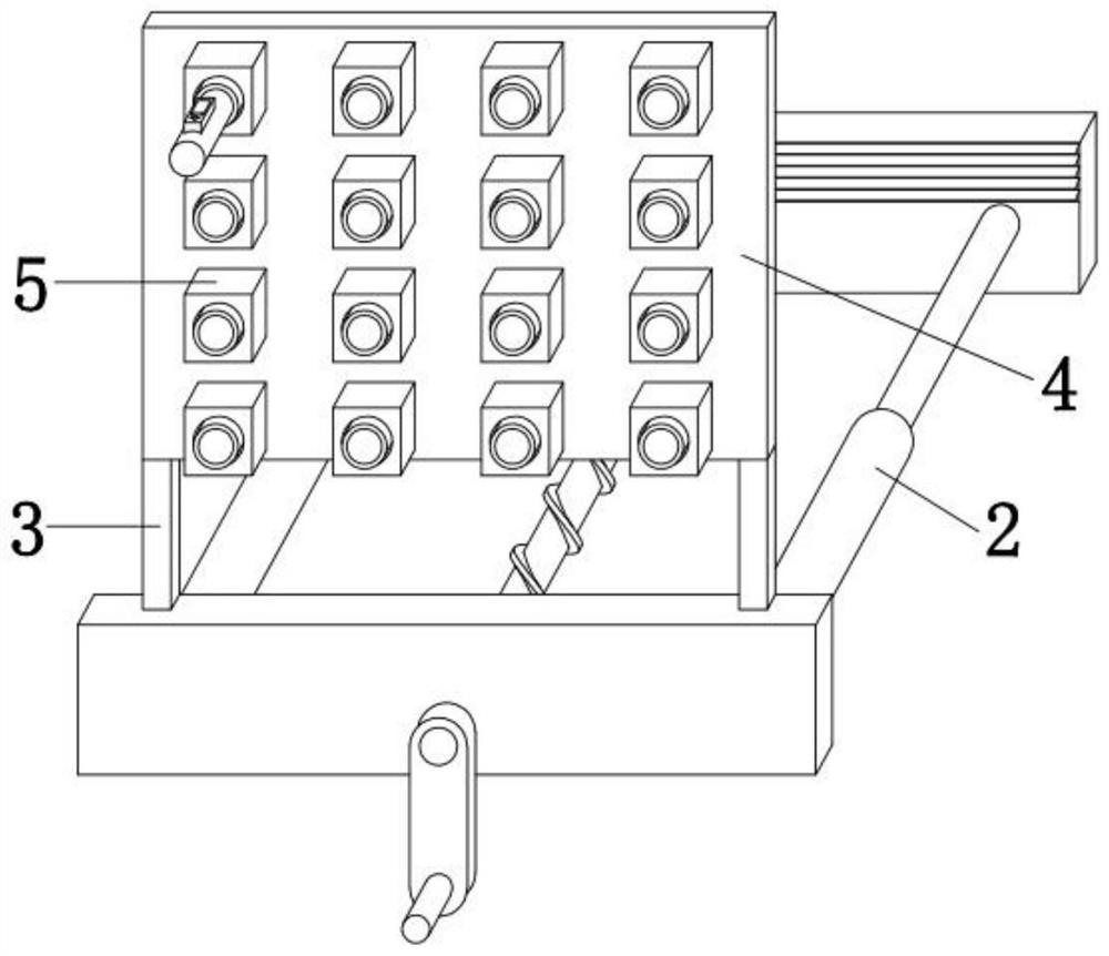
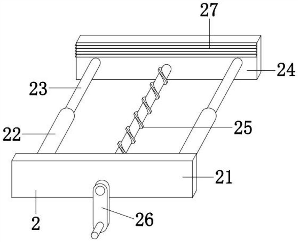
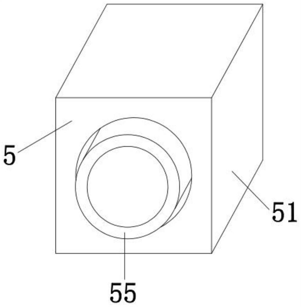
[0035] See Figure 1-5 , The present invention provides a technical solution: a concrete rebound test auxiliary device for surveying and mapping engineering, comprising a fixing mechanism 2, a supporting rod 3, a base plate 4 and a boosting mechanism 5. The two supporting rods 3 are respectively detachably arranged in the fixing mechanism On the left and right ends of the top front side of 2, the base plate 4 is detachably arranged on the top of the support rod 3, and the booster mechanism 5 is fixed by the base plate 3. The twelve booster mechanisms 5 are detachably arranged in front of the base plate 4 from top to bottom. The twelve boosting mechanisms 5 are arranged in four rows and four columns.
[0036] As a preferred solution, furthermore, the fixing mechanism 2 includes a support plate 21, a sleeve 22, a sliding rod 23, a splint 24, a screw 25 and a rocking handle 26. The top of the support plate 21 is detachably connected to the bottom of the support rod 3. Two sleeves 22 are fixedly connected to the left and right ends of the rear side of the support plate 21, one end of the sliding rod 23 is inserted into the inner cavity of the sleeve 22, and the clamping plate 24 is limited by the cooperation of the sleeve 22 and the sliding rod 23 to ensure The splint 24 can move linearly back and forth. The splint 24 is detachably arranged at the other end of the sliding rod 23. The combined force of the splint 24 and the support plate 21 can fix the fixing mechanism 2 on the beam or column of the building. One end of the screw 25 passes through a bearing It is rotatably connected to the middle of the front side of the splint 24, and the other end of the screw 25 is screwed to the support plate 21. When the screw 25 rotates clockwise or counterclockwise, the screw 25 can pull the splint 24 forward or backward while rotating. Move to change the distance between the clamping plate 24 and the supporting plate 21, and the rocking handle 26 is detachably arranged at the front end of the screw 25.
[0037] As a preferred solution, further, the boosting mechanism 5 includes a positioning cylinder 51, a slide 52, a sliding block 53, a spring 54 and a boosting sleeve 55. The positioning cylinder 51 is detachably arranged on the front side of the base plate 4, and the positioning cylinder 51 The inner wall is provided with slideways 52 along the circumferential direction, and the booster sleeve 55 is restricted by the cooperation of the slideways 52 and the slider 53 to prevent the booster sleeve 55 from escaping from the positioning cylinder 51. The slider 53 and the spring 54 are inserted in from front to back In the inner cavity of the slide 52, the spring 54 is a rotary spring with an elastic coefficient of 45N/CM. The spring 54 is stretched or squeezed to produce elastic deformation, and returns to the initial state after removing the external force. The spring 54 uses its own elastic force to help The push sleeve 55 can be at the front side of the inner cavity of the positioning cylinder 51 when no external force is applied. The boost sleeve 55 is detachably arranged on the inner side of the sliding block 53, and the boost sleeve 55 is mated and plugged with the positioning cylinder 51 to boost The inner cavity of the sleeve 55 is tapered to ensure that the inner cavity of the booster sleeve 55 can be aligned with the outer wall of the concrete rebound tester, and the concrete rebound tester can be positioned.
[0038] As a preferred solution, furthermore, the supporting plate 21 and the back wall of the base plate 4 are on the same plane. When the supporting plate 21 is clamped on the beam or column of the building, the base plate 4 can be attached to the concrete wall. Ensure the stability of the substrate 4.
[0039] As a preferred solution, further, the back side of the support plate 21 and the front side of the splint 24 are provided with anti-skid ribs 27 from top to bottom. The anti-skid ribs 27 can increase the support plate 21 and the splint 24 to be clamped on the beam or column. The friction on the surface improves stability.
[0040] As a preferred solution, furthermore, the height of the screw 25 in the vertical direction is lower than the highest point of the outer wall of the sleeve 22 to ensure that the sleeve 22 can first contact the concrete wall and avoid the screw 25 from contacting the concrete wall and causing wear.
[0041] As a preferred solution, furthermore, the number of slides 52 is three, and the three slides 52 are distributed on the inner wall of the positioning cylinder 51 clockwise every 120 degrees, which can limit the booster sleeve 55 from three directions , To further improve the stability of the booster sleeve 55 when it moves.
[0042] The detailed connection method is a well-known technology in the field. The following mainly introduces the working principle and process. The specific work is as follows.
[0043] When in use, the support plate 21 and the splint 24 are located on the opposite side of the beam or column, and the sleeve 22 is attached to the beam or column, and the crank 26 is rotated clockwise to promote the screw 25 to rotate clockwise, because the screw 25 and the support plate 21 Threaded, the screw 25 can drive the splint 24 to move forward under the limit of the slide rod 23, and the distance between the splint 24 and the support plate 21 is gradually reduced until the support plate 21 and the splint 24 are clamped on the beam or column , The screw 25 and the support plate 21 are screwed tightly by the blocking action of the beam or column, so as to realize the fixation of the base plate 4. The debugged concrete rebound tester is inserted into the boosting sleeve 55 of the boosting mechanism 5 in turn, the boosting sleeve 55 pairs of concrete rebound testers are limited to ensure that the concrete rebound tester is perpendicular to the beam or column of the building, and the concrete rebound tester is pushed toward the concrete. The slider 53 slides along the inner wall of the slide 52 and squeezes the spring 54. Ensure that the working end of the concrete rebound tester is hit on the concrete vertically to achieve the strength test of the concrete. When the concrete rebound tester is retracted, the spring 54 can push the slider 53 under its own elastic force to assist The sleeve 55 is returned to its position to facilitate the reuse of the booster mechanism 5, so that there is no need to manually mark the beam or column for rebound test, which saves time and effort and ensures that the concrete rebound tester can pierce the concrete wall and beam vertically. Or the concrete strength detection accuracy of the column is high, which is beneficial to determine the overall stability of the building, and can meet the strength test requirements of the building beam or column.
[0044] Although the embodiments of the present invention have been shown and described, those of ordinary skill in the art can understand that various changes, modifications, and substitutions can be made to these embodiments without departing from the principle and spirit of the present invention. And variations, the scope of the present invention is defined by the appended claims and their equivalents.

PUM

no PUM

Description & Claims & Application Information

We can also present the details of the Description, Claims and Application information to help users get a comprehensive understanding of the technical details of the patent, such as background art, summary of invention, brief description of drawings, description of embodiments, and other original content. On the other hand, users can also determine the specific scope of protection of the technology through the list of claims; as well as understand the changes in the life cycle of the technology with the presentation of the patent timeline. Login to view more.

Similar technology patents

Construction and installation method of floor drain

Owner:宁波江北峰尚环保设备有限公司

Classification and recommendation of technical efficacy words

  • accurate location
  • Guaranteed accuracy
Why Eureka
Try Eureka