Voltage increasing regulator

A regulator and voltage technology, which is applied in the direction of adjusting electrical variables, control/regulation systems, instruments, etc., can solve the problems of complex structure, inability to stabilize voltage, and no detection function of voltage increase regulators, and achieve simple structure, The effect of increasing voltage and stabilizing voltage

Pending Publication Date: 2020-11-06
河南子阳电力科技有限公司
View PDF0 Cites 0 Cited by
  • Summary
  • Abstract
  • Description
  • Claims
  • Application Information

AI Technical Summary

Problems solved by technology

[0002] As the name suggests, a voltage booster is a device that increases the voltage. It can boost the voltage of some factories and household power terminals whose power voltage is lower than the normal value to a normal value or higher. The working principle of the voltage booster is to use the principle of electromagnetic induction. , electricity generation, magnetism generation, combination of frequency reduction and frequency increase, changing the inductance of electrical appliances, changing the capacitance of transmission wires and equipment, reducing line loss, reducing reactive power and finally increasing voltage, but the existing voltage increasing regulator has a complicated structure , does not have the detection function, and cannot perform the function of stabilizing the pressure. The device has a large structure and must be installed in a fixed position during installation.

Method used


Image

  • Voltage increasing regulator
  • Voltage increasing regulator
  • Voltage increasing regulator

Examples


Embodiment Construction

[0018] The following will clearly and completely describe the technical solutions in the embodiments of the present invention with reference to the accompanying drawings in the embodiments of the present invention. Obviously, the described embodiments are only some, not all, embodiments of the present invention. Based on the embodiments of the present invention, all other embodiments obtained by persons of ordinary skill in the art without making creative efforts belong to the protection scope of the present invention.

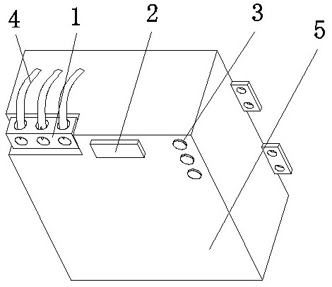
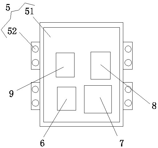
[0019] see Figure 1-3 , the present invention provides a technical solution: a voltage increasing regulator, including a housing assembly 5, the upper end of the housing assembly 5 is provided with a three-phase terminal block 1, the three-phase terminal block 1 is connected to an external power supply 4, and the external power supply 4 is an electric power The three-phase circuit of power supply, the upper end of shell assembly 5 is provided with control swi...


PUM


Abstract

The invention discloses a voltage increasing regulator. The regulator comprises a shell assembly, one side of the upper end of the shell assembly is provided with a three-phase wiring seat, the three-phase wiring seat is connected with an external power supply, the upper end of the shell assembly is provided with a control switch, and the shell assembly is internally provided with an internal power supply, a current sampling assembly, an electronic control circuit and a UFC electric energy regulator; the output end of the external power supply is electrically connected with the input end of the control switch; the output end of the control switch is electrically connected with the input end of an internal power supply; a circuit of the self-coupling coil is switched on by switching on theelectronic switch; then, the voltage can be increased through the self-coupling coil; the voltage increasing regulator is simple in structure, the device is more convenient to produce, the voltage ofan electric appliance can be effectively increased, so that the effects of stabilizing the voltage and increasing the voltage are achieved, the situation that overload operation is generated on equipment due to low voltage is reduced, and the function of protecting the electric equipment is achieved.

Description

technical field [0001] The invention relates to the technical field of voltage regulators, in particular to a voltage increasing regulator. Background technique [0002] As the name suggests, a voltage booster is a device that increases the voltage. It can boost the voltage of some factories and household power terminals whose power voltage is lower than the normal value to a normal value or higher. The working principle of the voltage booster is to use the principle of electromagnetic induction. , electricity generation, magnetism generation, combination of frequency reduction and frequency increase, changing the inductance of electrical appliances, changing the capacitance of transmission wires and equipment, reducing line loss, reducing reactive power and finally increasing voltage, but the existing voltage increasing regulator has a complex structure , does not have the detection function, and cannot perform the function of stabilizing the pressure. The structure of the ...

Claims


Application Information

Patent Timeline
Patent Type & Authority Applications(China)
IPC IPC(8): G05F1/56
CPCG05F1/56
Inventor 刘传仁王世钰冯鹏刘玲马衡衡魏恒中
Owner 河南子阳电力科技有限公司
Why Eureka
Try Eureka