Clutch, motor device, curtain control device and curtain

A technology for clutches and curtains, applied in the fields of clutches and curtains

Pending Publication Date: 2020-11-10
NINGBO SUNFREE MOTOR TECH CO LTD
View PDF0 Cites 3 Cited by
  • Summary
  • Abstract
  • Description
  • Claims
  • Application Information

AI Technical Summary

Problems solved by technology

[0004] Therefore, the embodiment of the present invention provides a clutch, a motor device, a curtain control device, and a curtain,...

Method used


Image

  • Clutch, motor device, curtain control device and curtain
  • Clutch, motor device, curtain control device and curtain
  • Clutch, motor device, curtain control device and curtain

Examples


no. 1 example

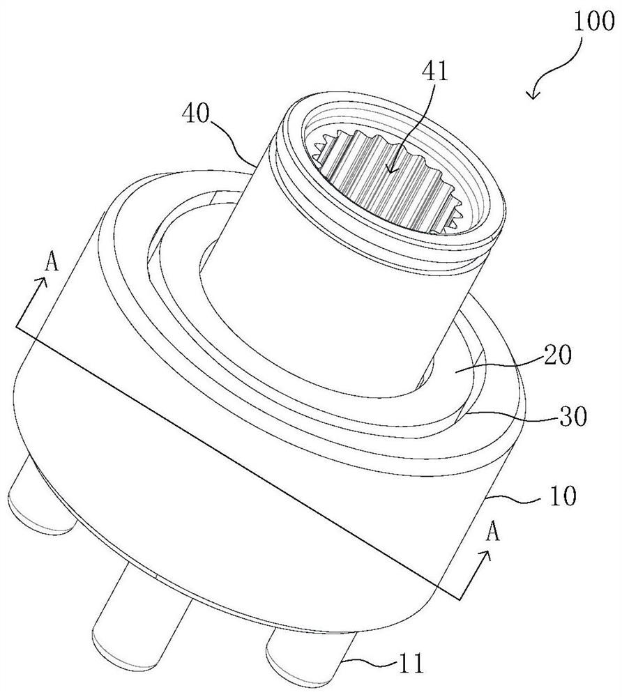
[0034] see figure 1 , which is a structural schematic diagram of a clutch 100 provided in the first embodiment of the present invention. The clutch 100 includes, for example: a driving force receiving part 10, a driving force output part 40, a driving force receiving part 10 and a driving force output The transmission part 20 between the parts 40, and the clutch control part 30 between the driving force receiving part 10 and the transmission part 20; wherein, the driving force receiving part 10 can cooperate with the driving force output part 40 through the clutch control part 30 to Drive the driving force output part 40 to rotate; the driving force receiving part 10 can also be separated from the driving force output part 40 through the clutch control part 30 , so that the driving force output part 40 can rotate relative to the transmission part 20 .

[0035] Wherein, the driving force receiving part 10 is connected with a driving force connector 11, for example, and the driv...

no. 2 example

[0047] see Figure 9 , which is a motor device provided in the second embodiment of the present invention. The motor device 200 includes, for example, the clutch 100 as described in the first embodiment and the motor body 210 connected to the clutch 100.

[0048] Specifically, the motor body 210 has a driving shaft 211 for outputting driving force, and the driving shaft 211 is connected to the driving force receiving part 10 of the clutch 100 . For example, the driving force receiving part 11 provided on the driving force receiving part 10 is a connecting shaft hole, and the driving shaft 211 is inserted into the connecting shaft hole, so that the motor body 211 can output the forward or reverse driving force to the driving force. Receiver 10.

[0049] The driving force output portion 60 of the clutch 100, for example, can also be provided with an output connection position 61 (see figure 1 and figure 2 ), the output connection position 64 can be connected with the driving...

no. 3 example

[0052] see Figure 10 , which is a curtain control device provided in the third embodiment of the present invention, the curtain control device 300 includes, for example: the motor device 200 as described in the second embodiment, the first winding reel 310, the second winding reel 320 and curtain control rope 330.

[0053] Specifically, the first winding reel 310 is connected to the driving force output portion 60 of the motor device 200 , specifically, the first winding reel 310 may be connected to the driving force output shaft 65 . There is a certain distance between the first wire reel 320 and the first wire reel 310 , and the curtain control rope 330 is wound between the first wire reel 310 and the first wire reel 320 . For example, the motor device 200 drives the first wire reel 310 to rotate through the driving force output part 60 , and the first wire reel 310 drives the first wire reel 320 to rotate through the curtain control rope 330 .

[0054] For example, the f...


PUM


Abstract

The embodiment of the invention discloses a clutch, a motor device, a curtain control device and a curtain. The clutch comprises a driving force output portion, a transmission portion, a driving forcereceiving portion, a clutch control portion, separate containing areas and clutch pieces, wherein the transmission portion is connected to the driving force output portion in a sleeving mode and is provided with clutch piece mounting positions; the driving force receiving portion is arranged at the side, away from the driving force receiving portion, of the transmission portion and is provided with a driving force conduction piece; the clutch control portion is arranged at one side of the driving force receiving portion and comprises a combining piece located on the driving force receiving portion; the separate containing areas are arranged between two combining surfaces; and the clutch pieces are arranged in the clutch piece mounting positions in the transmission portion. According to the embodiment, problems brought by the situation that an existing clutch achieves separation and combination functions by adopting a magnetic separation mode are effectively solved.

Description

technical field [0001] The invention relates to the technical field of clutch control, in particular to a clutch, a motor device, a curtain control device and a curtain. Background technique [0002] Clutches, as the basic components in mechatronic mechanical transmission, usually use magnetic separation to realize the clutch function. The main way to realize the clutch function is the electromagnetic principle or magnetic components. In particular, the mechanical clutch mainly uses magnetic beads to realize the clutch function. Function. In doing so, the structure of the clutch is relatively simple, and the magnetism is easier to control. [0003] However, a clutch that uses an electromagnet to realize the clutch function has a relatively large volume and is difficult to reduce; while a clutch that uses a magnetic component to realize the clutch function has the problem of demagnetization of the magnetic component. Contents of the invention [0004] Therefore, the embod...

Claims


Application Information

Patent Timeline
IPC IPC(8): F16D41/066F16D41/064F16D41/06A47H5/02E06B9/322E06B9/68
CPCF16D41/066F16D41/064F16D41/06A47H5/02E06B9/322E06B9/68E06B9/70A47H5/0325F16D41/067E05Y2600/13E05Y2800/232F16D23/12F16D28/00
Inventor 姜春周永强
Owner NINGBO SUNFREE MOTOR TECH CO LTD
Why Eureka
Try Eureka