Pressure reducing valve

A technology of pressure reducing valve and valve seat, applied in the field of pressure reducing valve, can solve the problems of unstable outlet pressure, unable to achieve reliable sealing, air leakage, etc., and achieve the effect of improving sealing performance

Pending Publication Date: 2020-11-10
富莱姆测控新技术研究(上海)有限公司
View PDF0 Cites 2 Cited by
  • Summary
  • Abstract
  • Description
  • Claims
  • Application Information

AI Technical Summary

Problems solved by technology

The existing pressure reducing valve works outdoors for a long time in winter in Northeast China, and its temperature will reach minus 40 degrees. stable phenomenon

Method used


Image

  • Pressure reducing valve
  • Pressure reducing valve

Examples


Embodiment Construction

[0028] The present invention will be further elaborated below by describing a preferred specific embodiment in detail in conjunction with the accompanying drawings.

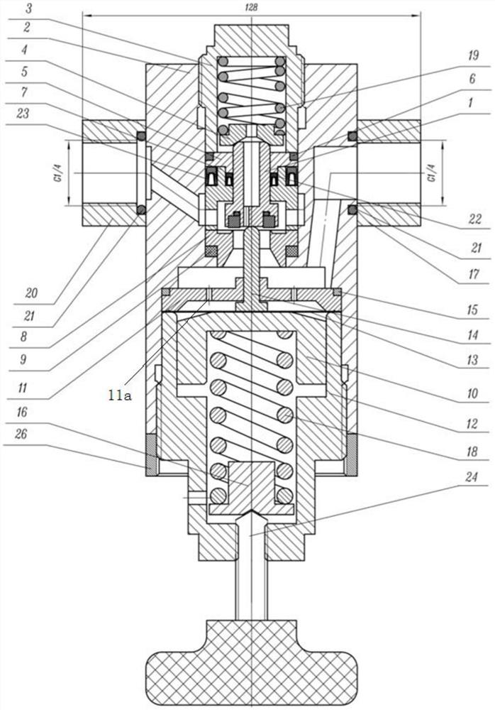
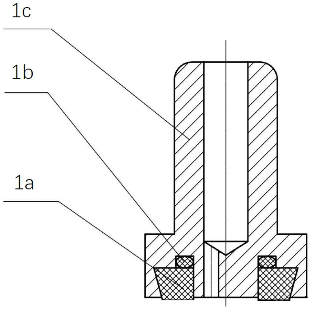
[0029] Such as figure 1 As shown, a pressure reducing valve includes: a housing 2, the housing is provided with an inlet and an outlet, and an auxiliary spring seat 4 is provided at the end position; a valve seat 8 is arranged in the housing 2 The spool assembly 1, the spool assembly 1 is arranged on the valve seat 8, and the top is provided with a secondary spring cover 3, the secondary spring cover 3 and the secondary spring seat 4 are provided with a secondary spring 19, and the secondary spring cover 3 and the secondary spring seat 4 are provided with a secondary spring 19. The spring exerts a downward pre-tightening force on the spool assembly; the damping disc is arranged below the spool assembly, and the damping disc 11 is provided with several feedback holes 11a along the circumferential direction; the th...


PUM


Abstract

The invention discloses a pressure reducing valve which comprises a shell, a valve seat, a valve element assembly, a damping disc, an ejector pin, a diaphragm, a main spring seat, a main spring, a supporting disc and an adjusting piece; the shell is provided with an inlet and an outlet, and an auxiliary spring seat is arranged at the end of the shell; the valve seat is arranged in the shell; the valve element assembly is arranged on the valve seat, an auxiliary spring outer sleeve is arranged at the top of the valve element assembly, auxiliary springs are arranged on the auxiliary spring outersleeve and the auxiliary spring seat, and the auxiliary springs apply downward pre-tightening force to the valve element assembly; the damping disc is arranged below the valve element assembly, and aplurality of feedback holes are formed in the damping disc in the circumferential direction; the diaphragm is arranged below the damping disc, one end of the ejector pin makes contact with one side of the diaphragm, and the other end of the ejector pin penetrates through the damping disc to abut against the bottom of the valve element assembly; the main spring is arranged between the main springseat and the supporting disc, and the supporting disc makes contact with the other side of the diaphragm; and the adjusting piece is connected to the main spring seat.

Description

technical field [0001] In particular, the invention relates to a pressure relief valve. Background technique [0002] The pressure reducing valve is often used in occasions where it is necessary to reduce the pressure of the gas source and provide a stable pressure or flow of gas. It is used to reduce the unstable inlet pressure and stabilize it within a certain range. The existing pressure reducing valve works outdoors for a long time in winter in Northeast China, and its temperature will reach minus 40 degrees. stabilization phenomenon. Contents of the invention [0003] The purpose of the present invention is to provide a pressure reducing valve, which can accurately control the pressure of the outlet gas and adapt to the low temperature working environment. [0004] In order to achieve the above object, the present invention is achieved through the following technical solutions: [0005] A pressure reducing valve is characterized in that it comprises: [0006] A ho...

Claims


Application Information

Patent Timeline
Patent Type & Authority Applications(China)
IPC IPC(8): F16K17/32F16K31/126F16K31/128F16K1/36
CPCF16K1/36F16K17/32F16K31/126F16K31/128
Inventor 卢志勇朱剑青
Owner 富莱姆测控新技术研究(上海)有限公司
Why Eureka
Try Eureka