Automatic testing method and system for smoke-sensing fire detector

An automated testing, smoke-sensing fire technology, applied in the direction of fire alarms, instruments, measuring devices that rely on the effect of smoke/gas, can solve the problems of manpower and time, low efficiency, etc., save manpower and time, improve The effect of inspection efficiency, shortening of waiting time and delivery cycle

Pending Publication Date: 2020-11-10
深圳市研测认证检测有限公司
View PDF0 Cites 1 Cited by
  • Summary
  • Abstract
  • Description
  • Claims
  • Application Information

AI Technical Summary

Problems solved by technology

At present, the testing work is manually triggered, so the staff needs to be present all the time in order to trigger a new round of testing work in time, which consumes a lot of manpower and time and is inefficient

Method used


Image

  • Automatic testing method and system for smoke-sensing fire detector
  • Automatic testing method and system for smoke-sensing fire detector
  • Automatic testing method and system for smoke-sensing fire detector

Examples


Embodiment 1

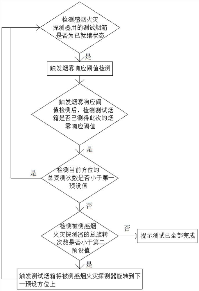
[0021] An embodiment of the present invention provides an automatic test method for a smoke detector, such as figure 1 shown, including the following steps:

[0022] Detect whether the test smoke box used for the smoke detector is in the ready state, and if so, trigger the smoke response threshold detection.

[0023] In this embodiment, in order to make the detection work more reliable, before triggering the smoke response threshold detection:

[0024] Test the smoke response threshold value measured by the first fire alarm controller reset of the smoke box;

[0025] After the smoke response threshold is cleared, the smoke box host of the test smoke box switches to the state to be triggered to detect the smoke response threshold.

[0026] In this embodiment, in order to avoid the situation that the flue is not cleaned in time, if the test smoke box is not in the ready state, the test smoke box is triggered to clean the flue.

[0027] In this embodiment, in order to realize ...

Embodiment 2

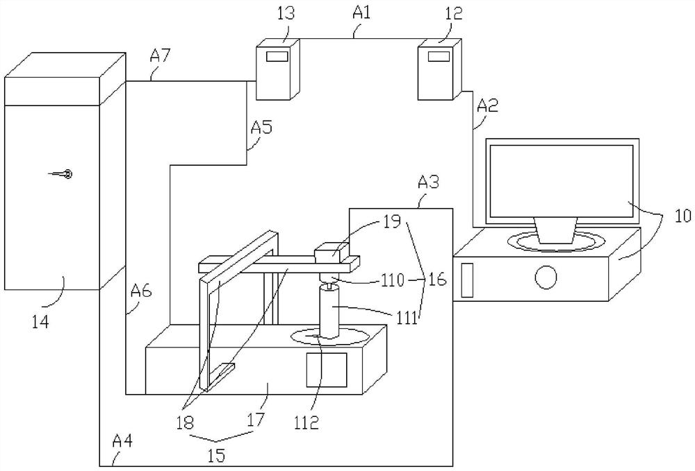
[0037] An embodiment of the present invention provides an automatic test system for a smoke detector, based on the automatic test method for a smoke detector provided in Embodiment 1, such as figure 2 shown, including:

[0038] Industrial control computer 10, and the test smoke box that smoke sense fire detector is used; The stepping motor driving assembly 16 that is rotated by the detected smoke fire detector in the box main body 15; the first fire alarm controller 12, the stepping motor driving assembly 16 and the smoke box host 14 are all electrically connected with the industrial control computer 10 and controlled by it. control; the smoke box main body 15 and the second fire alarm controller 13 are all communicated with the smoke box host 14; the first fire alarm controller 12 is connected with the second fire alarm controller 13; the second fire alarm controller 13 is connected with the Smoke box main body 15 communication connection;

[0039] The industrial control c...


PUM


Abstract

The invention relates to an automatic test method and system for a smoke-sensing fire detector, and the method comprises the steps: detecting whether a test smoke box for the smoke fire detector is ina ready state or not, and triggering smoke response threshold detection if the test smoke box is in the ready state; after smoke response threshold detection is triggered, detecting whether the smokeresponse threshold of this time is measured by the test smoke box, and if so, detecting whether the total number of times of detection in the current direction is smaller than a first preset value; if the total number of times of detection is smaller than the first preset value, skipping to the step of detecting whether the smoke fire detector is ready or not, otherwise, detecting whether the total number of rotation times of the detected smoke fire detector is smaller than a second preset value or not; if the total number of rotation times is smaller than a second preset value, triggering the test smoke box to rotate the smoke fire detector to be tested to the next preset direction, and skipping to the step of detecting whether the smoke fire detector is ready or not after rotation, otherwise, prompting that the test is completed completely; therefore, automatic triggering can be achieved, testing can still be conducted under the unattended condition, and the detection efficiency isimproved.

Description

technical field [0001] The invention relates to the technical field of testing smoke detectors, and more specifically, to an automatic testing method and system for smoke detectors. Background technique [0002] According to "GB4715 Point Type Smoke Detector Technical Requirements and Test Methods", the smoke detector needs to complete the corresponding azimuth test (that is, rotate 45° around its own axis each time, and rotate 8 times in total to measure 8 azimuths. The smoke response threshold above) and the repeatability test (that is, the same position needs to measure the smoke response threshold 6 times), it takes about 4 hours to complete the test of a smoke fire detector. At present, the testing work is manually triggered, so the staff needs to be present all the time to trigger a new round of testing work in time, which consumes a lot of manpower and time and is inefficient. Contents of the invention [0003] The technical problem to be solved by the present inve...

Claims


Application Information

Patent Timeline
Patent Type & Authority Applications(China)
IPC IPC(8): G08B17/10G01N33/00G01N15/06
CPCG01N15/06G01N33/0006G01N33/0063G08B17/10
Inventor 张良帅方泽伟舒伟龙
Owner 深圳市研测认证检测有限公司
Why Eureka
Try Eureka