
Optical lens and optical apparatus

A technology of optical lenses and lens groups, applied in the field of optical lenses, can solve problems that do not necessarily meet the requirements for the use of spectroscopic components

Active Publication Date: 2020-11-10
SHEN ZHEN HYPERNANO OPTICS TECH CO LTD
View PDF5 Cites 0 Cited by
  • Summary
  • Abstract
  • Description
  • Claims
  • Application Information

AI Technical Summary

Problems solved by technology

The spectroscopic element also has special requirements for the camera used with it. The premise is that it does not affect the spectral resolution. Currently, the cameras on the market are mostly used for imaging, which may not meet the requirements of the spectroscopic element, and the available wavelength bands may not be able to meet the hyperspectral requirements. Imaging Band Requirements

Method used


Image

  • Optical lens and optical apparatus
  • Optical lens and optical apparatus
  • Optical lens and optical apparatus

Examples


Embodiment Construction

[0033] In the following detailed description, reference is made to the accompanying drawings, which form a part hereof, and which show by way of illustration specific embodiments in which the invention may be practiced. In this regard, directional terms such as "top", "bottom", "left", "right", "upper", "lower", etc. are used with reference to the orientation of the figures being described. Because components of an embodiment may be positioned in several different orientations, directional terminology is used for purposes of illustration and is by no means limiting. It is to be understood that other embodiments may be utilized or logic changes may be made without departing from the scope of the present invention. The following detailed description should therefore not be taken in a limiting sense, and the scope of the invention is defined by the appended claims.

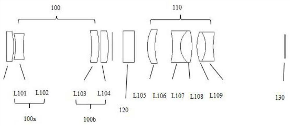
[0034] Figure 1a A schematic structural diagram of an optical lens according to an embodiment of the present inv...


PUM


Abstract

An optical lens and optical apparatus are disclosed. The optical lens comprises a first lens group, a second lens group and an imaging sensor in sequence from an object side to an imaging side along an optical axis, and further comprises a light splitting element arranged between the first lens group and the imaging sensor, the first lens group is used for collimating light after a to-be-measuredobject plane enters the lens, the first lens group comprises a front lens group and a rear lens group, the front lens group has negative diopter, the rear lens group has positive diopter, the second lens group comprises a lens group with a symmetrical double-gluing structure, and the light splitting element and the second lens group are used for imaging collimated light rays on the imaging sensoraccording to different wave bands. The optical lens is compact and small in size, can be applied to a hyperspectral imaging and detection camera, and has very high practicability.

Description

technical field [0001] The invention relates to the field of optical lenses, and in particular to an optical lens and optical equipment. Background technique [0002] The camera lens can collect external light and image it on the sensor, but this method can only observe the appearance characteristics of the object to be tested, and cannot detect and analyze its components. One dimension—spectral dimension, to objectively view and analyze the captured objects, and apply it to different occasions according to different needs. [0003] Hyperspectral imaging detection systems generally include components such as illumination and spectroscopic imaging, and the spectroscopic methods are generally grating spectroscopic or interference spectroscopic. The spectroscopic element also has special requirements for the camera used with it. The premise is that it does not affect the spectral resolution. Currently, the cameras on the market are mostly used for imaging, which may not meet t...

Claims


Application Information

Patent Timeline
IPC IPC(8): G01J3/28G01J3/02H04N5/225G02B7/04G02B13/00
CPCG01J3/2823G01J3/0208G01J3/021G02B13/006G02B7/04
Inventor 俞萍萍黄锦标郭斌
Owner SHEN ZHEN HYPERNANO OPTICS TECH CO LTD
Learn More