Water boiler

A water boiler and case technology, which is applied in kitchen utensils, household utensils, beverage preparation devices, etc., can solve the problem of ineffective heat exchange between the cold water tank and the heat exchange tube, the rapid rise of the water temperature in the cold water tank, and the inability of the heat exchange tube to be fast Cooling and other issues, to achieve the effect of reasonable layout, prolonging the time of continuous cooling, and slowing down the speed of water temperature rise

Pending Publication Date: 2020-11-13
NINGBO HAWK ELECTRICAL APPLIANCE CO LTD
View PDF2 Cites 4 Cited by
  • Summary
  • Abstract
  • Description
  • Claims
  • Application Information

AI Technical Summary

Problems solved by technology

[0006] The water boiler with the application number CN201610838375.4 can produce both hot water and warm water. Although it solves the problem that the water flowing out of the traditional water boiler cannot be drunk directly, there are still differences with the existing water boilers that can produce warm and hot water. same problem
[0007] Most of the existing warm and hot water boilers use heat exchange to cool the boiled water in the body, that is, a cold water tank is installed in the body, and the above-mentioned heat exchange tube is arranged in the cold water tank, and the boiling water flows into the heat exchange tube. Finally, it exchanges heat with the cold water outside the heat exchange tube, so that the boiling water in the heat exchange tube cools down, but the water in the cold water tank is not flowing water, and the water temperature of the cold water tank rises quickly. After several heat exchanges, the cold water tank and The heat exchange effect of the heat exchange tube is not obvious, and the heat exchange tube cannot cool down quickly. It is necessary to wait until the water temperature of the cold water tank comes down before continuing to cool down the heat exchange tube

Method used


Image

  • Water boiler
  • Water boiler
  • Water boiler

Examples


Embodiment

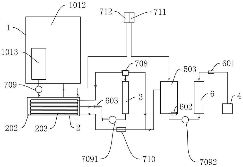
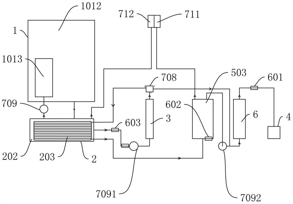
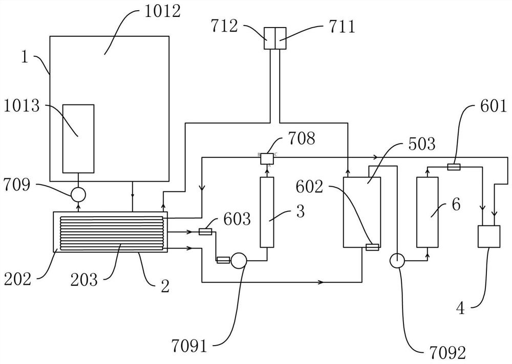
[0036] Such as Figure 1 to Figure 12 shown

[0037]A water boiling machine, comprising a chassis 707, and a water tank 1 located inside the chassis 707, a cooling chamber 2, a primary heating device 3, a water chamber 503, and a secondary heating device 6, the water tank 1 is detachably connected to the chassis 707, and the cooling chamber 2. Located below the water tank 1 and fixedly connected to the bottom of the cabinet 707. The water tank 1 is provided with an inner tank 11. The water tank 1 includes an outer chamber 1012 located outside the inner tank 11 and an inner chamber 1013 located in the inner tank 11. The outer chamber 1012 is connected to the inner tank 11. The chamber 1013 communicates, the bottom of the water tank 1 is provided with a first water outlet 10121 communicated with the outer chamber 1012, and a first water inlet 10131 communicated with the inner chamber 1013, and the cooling chamber 2 is provided with a cooling pipe 203 fixedly connected thereto, a...


PUM


Abstract

The invention discloses a water boiler. The water boiler includes a case, and also includes a water tank, a cooling bin, a primary heating device, a water passing bin and a secondary heating device that are located in the case. The water tank is detachably connected with the case, the cooling bin is located below the water tank and fixedly connected with the bottom of the case, an inner containeris arranged in the water tank, the water tank comprises an outer chamber located outside the inner container and an inner chamber located in the inner container, the outer chamber is communicated withthe inner chamber, a first water outlet communicated with the outer chamber and a first water inlet communicated with the inner chamber are formed in the bottom of the water tank, and a cooling pipefixedly connected with the cooling bin is disposed in the cooling bin. According to the water boiler, the water temperature rising speed of the cooling chamber can be reduced, the continuous cooling time of the cooling pipe is prolonged, and more warm water can flow out of the water boiler.

Description

technical field [0001] The invention relates to the technical field of water boiling machines, in particular to a water boiling machine. Background technique [0002] The water boiler is a device designed and developed to meet the needs of more people drinking boiled water by converting electrical energy or chemical energy into heat energy to heat boiled water. [0003] The patent for invention with the application number CN201210252597.X discloses a rapid boiling one-time boiling water machine, which includes a circulating water supply circuit, including a mobile water tank, a water outlet base, a three-way water pipe, a circulating water pump, a water supply pipe, and a liquid level tank connected in sequence and the return pipe; a liquid level limiter located in the circulating water supply circuit, including a liquid level tank, a water delivery pipe mouth plane and a return water pipe mouth plane located on both sides of the liquid level tank; a maintenance of the liqui...

Claims


Application Information

Patent Timeline
Patent Type & Authority Applications(China)
IPC IPC(8): A47J31/00A47J31/56A47J31/46A47J31/44
CPCA47J31/00A47J31/44A47J31/46A47J31/56
Inventor 陈剑伦
Owner NINGBO HAWK ELECTRICAL APPLIANCE CO LTD
Why Eureka
Try Eureka