
Steel mill waste residue treatment method

A processing method and steelmaking technology, applied in grain processing, chemical instruments and methods, cleaning devices, etc., can solve the problems of high labor intensity and low work efficiency, so as to reduce labor intensity, improve work efficiency, and improve adsorption effect Effect

Active Publication Date: 2020-11-13
SHANXI TONGCAI IND & TRADE
View PDF15 Cites 0 Cited by
  • Summary
  • Abstract
  • Description
  • Claims
  • Application Information

AI Technical Summary

Problems solved by technology

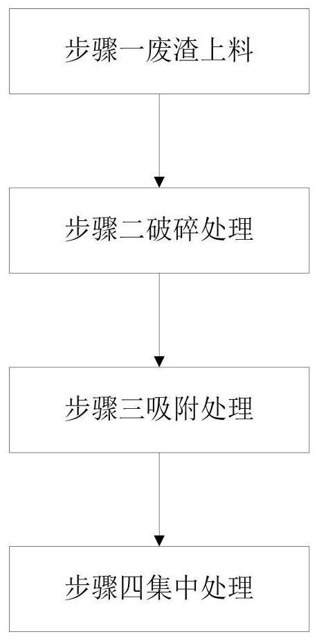
The steel slag contains a small amount of iron waste slag. In order to separate the iron waste slag from the steel slag, it is usually necessary to crush the steel slag and then proceed to the next step of separation process. The process of removing iron from the steel plant waste slag needs to go through Multiple processes such as waste slag feeding, crushing treatment, adsorption treatment and centralized treatment At present, the crushing process and separation process of steel slag are independent of each other, and frequent transfer of materials is required between the two processes, which is not only labor-intensive, but also low in efficiency

Method used


Image

  • Steel mill waste residue treatment method
  • Steel mill waste residue treatment method
  • Steel mill waste residue treatment method

Examples


specific Embodiment approach

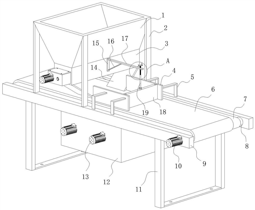
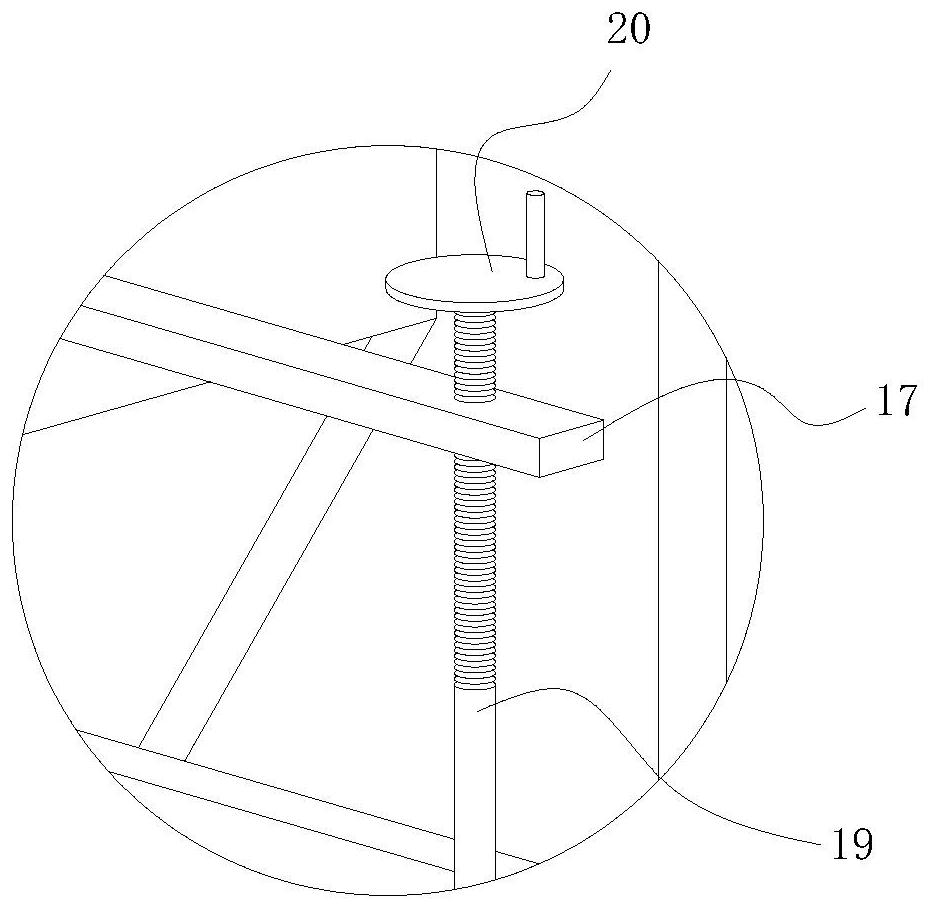
[0049] The specific embodiment: connect the circuit of the second motor 13 after the first motor 10, the first motor 10 drives the first belt roller 8 to rotate, and then the transmission belt 7 rotates between the first belt roller 8 and the second belt roller 22, The second motor 13 drives the brush roller 24 to rotate in the rectangular frame body 12, and the rotation direction of the brush roller 24 is opposite to the moving direction of the transmission belt 7, and the steel slag crushed by the biaxial crusher 3 falls to the bar with a magnet. 21 on the rubber pad 6, and when the first motor 10 drives the transmission belt 7 to rotate, the transmission belt 7 drives the rubber pad 6 to move together, so that the rubber pad 6 drives the crushed steel slag to move, and the iron content in the crushed steel slag is now The waste residue is attached to the surface of the rubber pad 6 under the adsorption of the magnet bar 21, and the rest of the waste residue is discharged fro...


PUM


Abstract

The invention relates to the technical field of waste residue treatment, and particularly relates to a steel mill waste residue treatment method which uses waste residue treatment equipment. The steelmill waste residue treatment equipment is used for treating steel mill waste residues and comprises multiple steps such as waste residue feeding, crushing treatment, adsorption treatment and centralized treatment. In the working process of the waste residue treatment equipment, steel slag crushed by a double-shaft crusher falls onto a rubber pad with a magnet strip, and a rotating transmission belt drives the rubber pad to move together, so that the rubber pad drives the crushed steel slag to move, iron waste residues in the crushed steel slag are attached to the surface of the rubber pad under the adsorption of the magnet strip at the moment, and the purpose of separating the iron waste residues is achieved; and when the rubber pad moves into a rectangular frame body, a rotating brush roller sweeps off the iron waste residues attached to the rubber pad to the ground on the lower side of the rectangular frame body, so that the integration of steel slag crushing and separation is realized, and the frequent transfer of the steel slag is avoided.

Description

technical field [0001] The invention relates to a method for treating waste slag in a steelmaking plant, belonging to the technical field of steel slag treatment. Background technique [0002] During the production process of steelmaking plants, steel slag containing impurities such as limestone and dolomite will be produced. The steel slag contains a small amount of iron waste slag. In order to separate the iron waste slag from the steel slag, it is usually necessary to crush the steel slag and then proceed to the next step of separation process. The process of removing iron from the steel plant waste slag needs to go through Multiple processes such as waste slag feeding, crushing treatment, adsorption treatment and centralized treatment At present, the crushing process and separation process of steel slag are independent of each other, and frequent transfer of materials is required between the two processes, which is not only labor-intensive, but also low in efficiency. ...

Claims


Application Information

Patent Timeline
Patent Type & Authority Applications(China)
IPC IPC(8): B03C1/18B03C1/30B65G45/18B02C4/28
CPCB03C1/18B03C1/30B65G45/18B02C4/28B02C2201/06
Inventor 祁小蒙
Owner SHANXI TONGCAI IND & TRADE
Learn More