Plate bending forming process

A forming process and plate rolling technology, which is applied in the direction of manufacturing tools, metal processing equipment, feeding devices, etc., can solve the problems of inconvenient welding operations, easy shaking, and large gaps at both ends, so as to avoid low welding efficiency and improve Molding efficiency, the effect of avoiding misalignment at both ends

Active Publication Date: 2020-11-13
佛山市金常旺不锈钢有限公司
View PDF6 Cites 11 Cited by
  • Summary
  • Abstract
  • Description
  • Claims
  • Application Information

AI Technical Summary

Problems solved by technology

[0003] For the coil forming of the thin plate, because the thin plate has a certain degree of elasticity, when the thin plate is rolled and formed, the two ends of the thin plate are not easy to align, and it is easy to shake, and the gap between the two ends after forming is large, which is inconvenient for welding. Thereby affecting the welding quality and the efficiency of coil forming; and when coiling, it is difficult to realize that the joints at both ends of the forming cylinder are just facing upwards. , at this time, the automatic welding operation cannot be realized, because welding is a precise operation process, once the welding position is wrong, it will directly cause the failure of welding;

Method used


Image

  • Plate bending forming process
  • Plate bending forming process
  • Plate bending forming process

Examples


Embodiment Construction

[0035] The following will clearly and completely describe the technical solutions in the embodiments of the present invention with reference to the accompanying drawings in the embodiments of the present invention. Obviously, the described embodiments are only some, not all, embodiments of the present invention. Based on the embodiments of the present invention, all other embodiments obtained by persons of ordinary skill in the art without making creative efforts belong to the protection scope of the present invention.

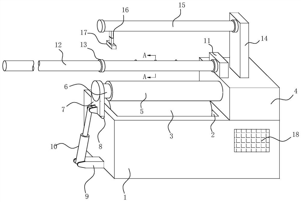
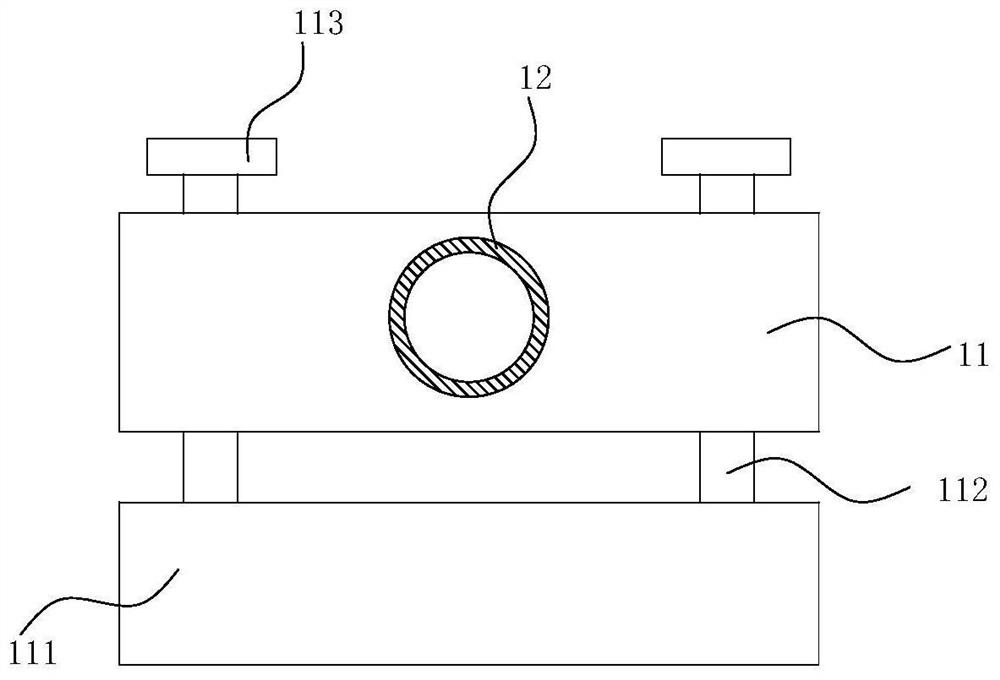
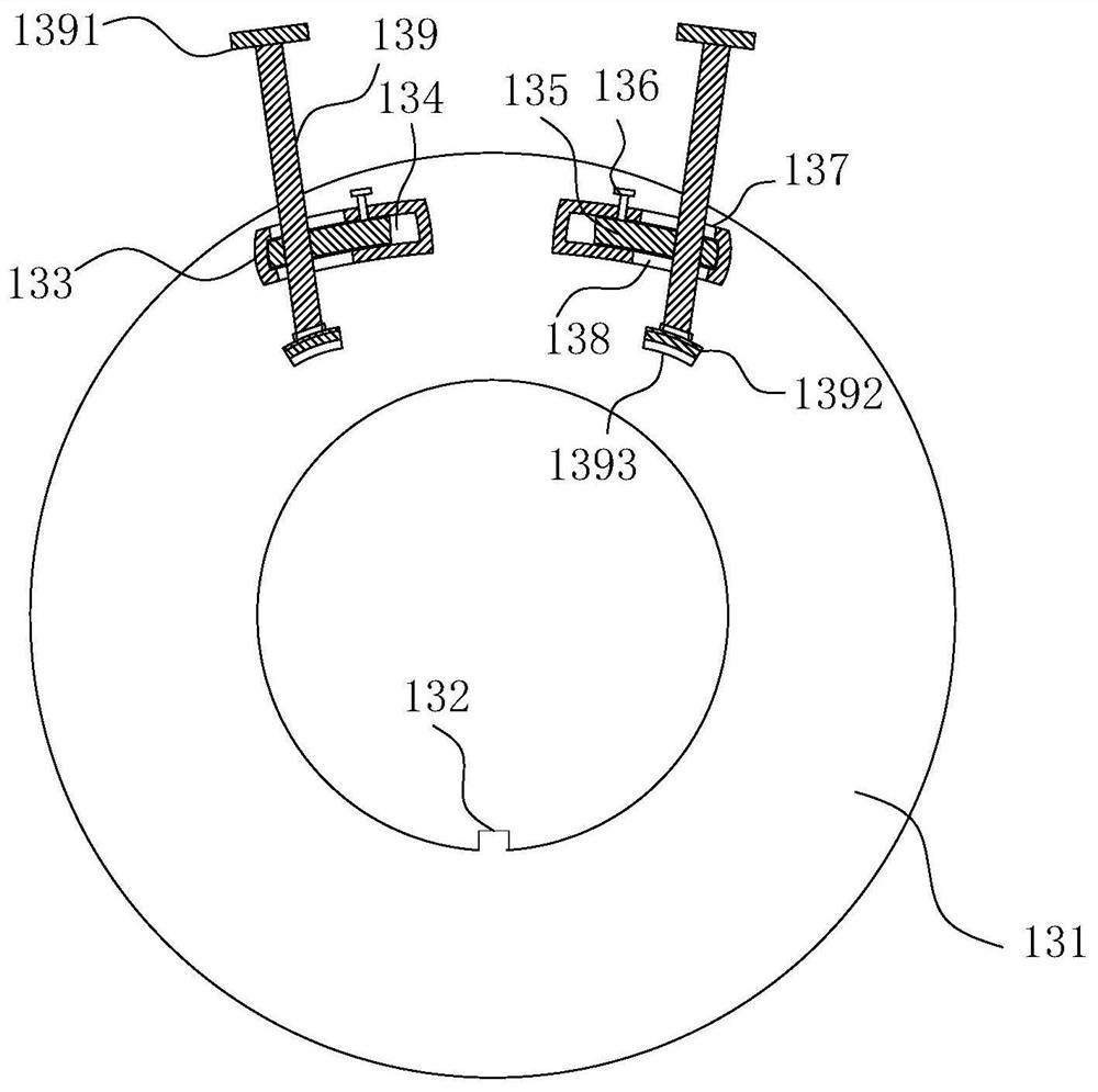
[0036] see Figure 1 to Figure 4 , the present invention provides a technical solution:

[0037] In the embodiments of the present invention, the terms "first" and "second" are used for description purposes only, and cannot be understood as indicating or implying relative importance. The terms "plurality" and "several" refer to two or more, unless otherwise clearly defined.

[0038] A coil forming process, comprising the following coil forming process steps:...


PUM


Abstract

The invention relates to the technical field of plate bending forming, in particular to a plate bending forming process. The plate bending forming process includes the following steps that S1, cuttingand blanking are carried out, and a plate is cut for blanking according to the process required dimensions; S2, plate bending is carried out, a plate bending machine with a quick positioning mechanism is used for bending the plate cut in the first step, and the quick positioning mechanism of the plate bending machine makes the connecting gap positions of the two ends of the bent plate be arrangedvertically upwards; S3, gap shrinkage is carried out, and the two ends of the bent plate are in precise contact by means of a gap shrinkage mechanism arranged on the plate bending machine; S4, welding is carried out, a laser welding mechanism is installed over the plate bending machine, and the laser welding mechanism is utilized to carry out laser welding at the joints of the two ends of the bent plate; and S5, discharging is carried out after the formed barrel is obtained. The plate bending forming process is ingenious in concept and high in practicability, through the cooperation effect ofthe gap shrinkage mechanism, the quick positioning mechanism and the welding mechanism, the formed barrel can be subjected to quick positioning, gap shrinkage and then rapid welding, and the plate bending forming process is wide in application range and suitable for use and popularization.

Description

technical field [0001] The invention relates to the technical field of coil forming, in particular to a coil forming process. Background technique [0002] The plate rolling machine is a kind of equipment that uses work rolls to bend and form the sheet material. It can form parts of different shapes such as cylindrical parts and conical parts. It is a very important processing equipment. The working principle of the plate rolling machine is through hydraulic pressure. Force, mechanical force and other external forces make the work rolls move, so that the plate is bent or rolled into shape. According to the rotation and position changes of the work rolls of different shapes, oval parts, arc parts, and cylindrical parts can be processed. parts etc. [0003] For the coil forming of the thin plate, because the thin plate has a certain degree of elasticity, when the thin plate is rolled and formed, the two ends of the thin plate are not easy to align, and it is easy to shake, an...

Claims


Application Information

Patent Timeline
Patent Type & Authority Applications(China)
IPC IPC(8): B21D5/14B21D43/00B23P15/00
CPCB21D5/14B21D43/003B23P15/00Y02E60/10
Inventor 薛继纲梁涛
Owner 佛山市金常旺不锈钢有限公司
Why Eureka
Try Eureka