Laser visualization processing method and system

A processing method and processing system technology, applied in laser welding equipment, metal processing equipment, manufacturing tools, etc., can solve problems such as inability to directly observe products, and achieve the effect of easy adjustment and improved verification efficiency

Active Publication Date: 2020-11-13
WUHAN HGLASER ENG CO LTD
View PDF17 Cites 3 Cited by
  • Summary
  • Abstract
  • Description
  • Claims
  • Application Information

AI Technical Summary

Problems solved by technology

[0005] The purpose of the present invention is to provide a laser visualization processing method and system, which solves the problem that craftsmen cannot directly observe the product from the graphic files when designing the galvanometer processing graphics, and need to frequently go back and forth between the industrial computer and the processing table.

Method used


Image

  • Laser visualization processing method and system
  • Laser visualization processing method and system
  • Laser visualization processing method and system

Examples


Embodiment 1

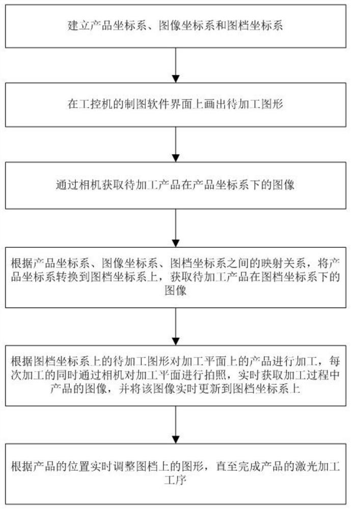
[0057] Such as figure 1 As shown, the present embodiment provides a laser visualization processing method, comprising the following steps:

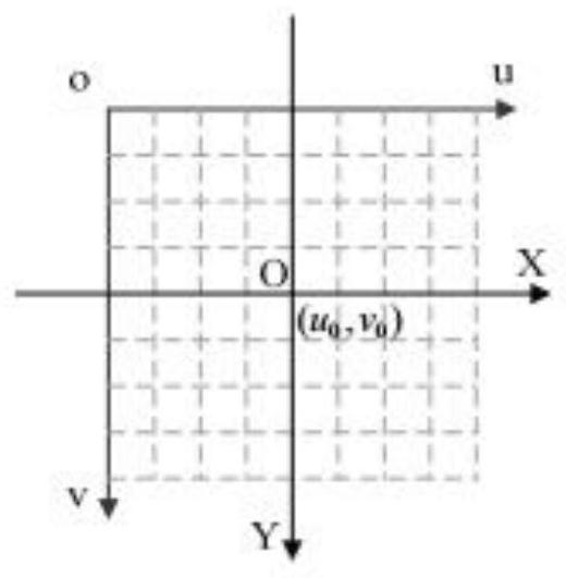
[0058] Establish product coordinate system, image coordinate system and picture file coordinate system respectively; Described product coordinate system is positioned on processing plane; Described image coordinate system is positioned at the image surface of camera; Described picture file coordinate system is positioned at the drawing software interface of industrial computer superior;

[0059] Draw the graphics to be processed on the drawing software interface of the industrial computer;

[0060] Obtain the image of the product to be processed in the product coordinate system through the camera;

[0061] According to the mapping relationship between the product coordinate system, the image coordinate system and the drawing coordinate system, the product coordinate system is converted to the drawing coordinate system, and the image of ...

Embodiment 2

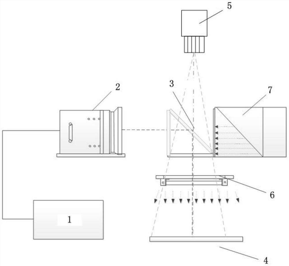
[0098] Such as figure 2 As shown, this embodiment provides a laser visualization processing system, including a laser 1, a galvanometer 2, a refractor 3 and a processing plane 4 arranged sequentially along the laser processing optical path; a camera 5 is arranged above the refractor 3; The processing plane 4 is arranged below the refractor 3, and an illuminating device is arranged between the processing plane 4 and the refracting mirror 3, and the illuminating device provides an illumination source for the processing plane 4; One side; the laser light emitted by the laser device 1 passes through the vibrating mirror 2 and the refracting mirror 3 to reach the processing plane 4 in turn, and the product is processed; the camera 5 acquires the image of the product on the processing plane 4 in real time, and the acquired image is real-time Update to the drawing file on the drawing software interface of the industrial control machine.

[0099] Specifically, the refractor 3 is a t...


PUM


Abstract

The invention discloses a laser visualization processing method and system. The processing method comprises the steps that a product coordinate system, an image coordinate system and a drawing file coordinate system are established correspondingly; a to-be-processed graph is drawn on a drawing software interface of an industrial personal computer; an image of a product under the product coordinatesystem is acquired through a camera; according to the mapping relation between the coordinate systems, the product coordinate system is converted to the drawing file coordinate system, and an image of the product under the drawing file coordinate system is obtained; the product is processed according to the to-be-processed graph on the drawing file coordinate system, meanwhile, a processing planeis photographed through the camera, an image of the product in the processing process is obtained in real time, and the image is updated to the drawing file coordinate system in real time; and the graph on the drawing file is adjusted in real time according to the position of the product until the laser processing procedure of the product is completed. According to the method, the problem that atechnician cannot directly observe a product from a drawing file and needs to frequently confirm between the industrial personal computer and a processing table top back and forth when designing a galvanometer processing graph is solved.

Description

technical field [0001] The invention belongs to the technical field of laser processing, in particular to a laser visualization processing method and system. Background technique [0002] At present, the combination of most laser processing systems and machine vision has become the norm in the laser industry. The vision system can guide the automatic positioning of the laser, including automatic detection to meet various production needs of customers. [0003] Common machine vision laser processing systems are divided into two types, one is that the galvanometer and the vision system are installed coaxially, and the other is that the galvanometer and the vision system are installed sideways, which can realize marking while observing To detect the effect of marking and adjust the parameters of laser processing, such as the patent with the publication number CN203380508U discloses a laser processing system with machine vision, including vibrating lens, field mirror, imaging d...

Claims


Application Information

Patent Timeline
Patent Type & Authority Applications(China)
IPC IPC(8): B23K26/00B23K26/70
CPCB23K26/00B23K26/702
Inventor 王雪辉路清彦王建刚
Owner WUHAN HGLASER ENG CO LTD
Why Eureka
Try Eureka