Auxiliary tool for automatic welding of automobile beam

An automatic welding and auxiliary tooling technology, applied in welding/cutting auxiliary equipment, auxiliary devices, welding equipment, etc., can solve the problems of small moving range, inconvenient manufacturing and use, lack of integration, etc., to achieve easy clamping and welding, To achieve the effect of precise adjustment

Inactive Publication Date: 2020-11-13
郑恩
View PDF8 Cites 1 Cited by
  • Summary
  • Abstract
  • Description
  • Claims
  • Application Information

AI Technical Summary

Problems solved by technology

[0002] Under the foundation of modern industry, automobiles have become an indispensable commodity for every household, which has also promoted the continuous progress of the automobile manufacturing industry, emphasizing the more intelligent and precise manufacturing process of each component. As we all know, the automobile frame is the An important load-bearing part on the vehicle, the manufacturing process of its structure is directly related to the production time and cost of the whole vehicle. In the traditional process, the clamping device and welding device of the automobile frame lack integration, which makes the entire mechanical structure too complicated and inconvenient. manufacture and use
[0003] However, the auxiliary tooling for automatic welding that has been put into use often has problems such as small moving range and insufficient integration. Therefore, we propose an auxiliary tooling for automatic welding of automobile girders.

Method used


Image

  • Auxiliary tool for automatic welding of automobile beam
  • Auxiliary tool for automatic welding of automobile beam
  • Auxiliary tool for automatic welding of automobile beam

Examples


Embodiment Construction

[0019] The following description serves to disclose the present invention to enable those skilled in the art to carry out the present invention. The preferred embodiments described below are only examples, and those skilled in the art can devise other obvious variations.

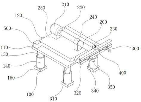
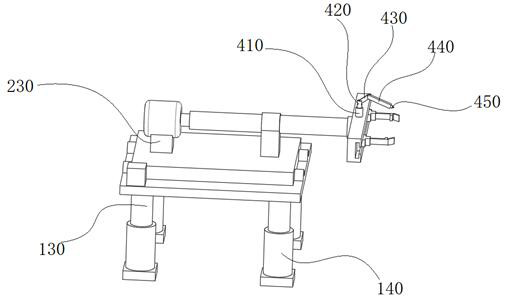
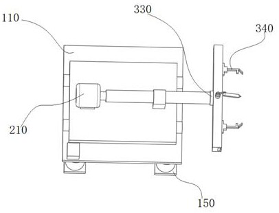
[0020] Please refer to figure 1 -As shown in -4, an auxiliary tooling for automatic welding of an automobile girder includes a support device 100, a rotating device 200, a clamping device 300, a welding device 400, and an integrated controller 500, and the support device 100 includes a base plate 110 and a fixed slideway 120 The rotating device 200 includes a rotating shaft 220 and an electric skateboard 250, and several fixed slideways 120 are slidingly fitted with the electric sliding board 250. The clamping device 300 includes a cross bar 310 and a rotating disc 330, and one end of the rotating shaft 220 rotates with the rotating disc 330. In cooperation, the welding device 400 includes a fixed round tab...


PUM


Abstract

The invention discloses an auxiliary tool for automatic welding of an automobile beam, and relates to the technical field of automatic welding. The auxiliary tool comprises a supporting device, a rotating device, a clamping device, a welding device and an integrated controller, wherein the supporting device comprises a bottom plate and fixed slideways, the rotating device comprises a rotating shaft and an electric sliding plate, the plurality of fixed slideways are in sliding fit with the electric sliding plate, the clamping device comprises a transverse rod and a rotating disc, one end of therotating shaft is in rotating fit with the rotating disc, the welding device comprises a fixed circular truncated cone, a first mounting groove is formed in one surface of the transverse rod, one endof the fixed circular truncated cone is connected with the first mounting groove, a first fixing groove is formed in the upper surface of a bottom plate, and the integrated controller is connected with the first fixing groove. According to the auxiliary tool, the fixed sliding way ensures that the rotating device can achieve long-distance movement in one direction, large-size beams are clamped and welded conveniently, the welding device is arranged on the transverse rod, the situation that redundant structures are additionally arranged to bear the welding device is avoided, and meanwhile, thewelding device is designed in a multi-section mode so that complex welding can be achieved at different angles.

Description

technical field [0001] The invention relates to the technical field of automatic welding, in particular to an auxiliary tooling for automatic welding of automobile girders. Background technique [0002] Under the foundation of modern industry, automobiles have become an indispensable commodity for every household, which has also promoted the continuous progress of the automobile manufacturing industry, emphasizing the more intelligent and precise manufacturing process of each component. As we all know, the automobile frame is the An important load-bearing part on the vehicle, the manufacturing process of its structure is directly related to the production time and cost of the whole vehicle. In the traditional process, the clamping device and welding device of the automobile frame lack integration, which makes the entire mechanical structure too complicated and inconvenient. manufacture and use. [0003] However, the auxiliary tooling for automatic welding that has been put ...

Claims


Application Information

Patent Timeline
IPC IPC(8): B23K37/02B23K37/04B23K37/047
CPCB23K37/0252B23K37/0435B23K37/047B23K2101/006
Inventor 郑恩
Owner 郑恩
Why Eureka
Try Eureka