
Edge polishing device and polishing method

A polishing device and edge technology, which is applied in the direction of surface polishing machine tools, grinding/polishing equipment, metal processing equipment, etc., can solve the problems of poor wafer edge, reduced friction, and reduced removal rate, and achieves constant removal rate , to avoid the effect of insufficient removal

Active Publication Date: 2020-11-13
XIAN ESWIN MATERIAL TECH CO LTD +1
View PDF11 Cites 4 Cited by
  • Summary
  • Abstract
  • Description
  • Claims
  • Application Information

AI Technical Summary

Problems solved by technology

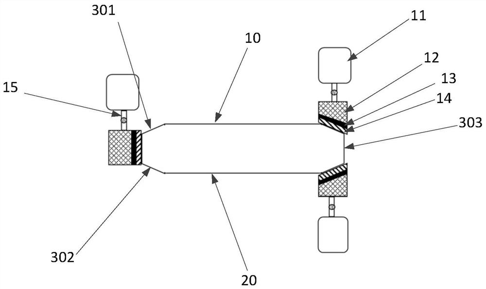
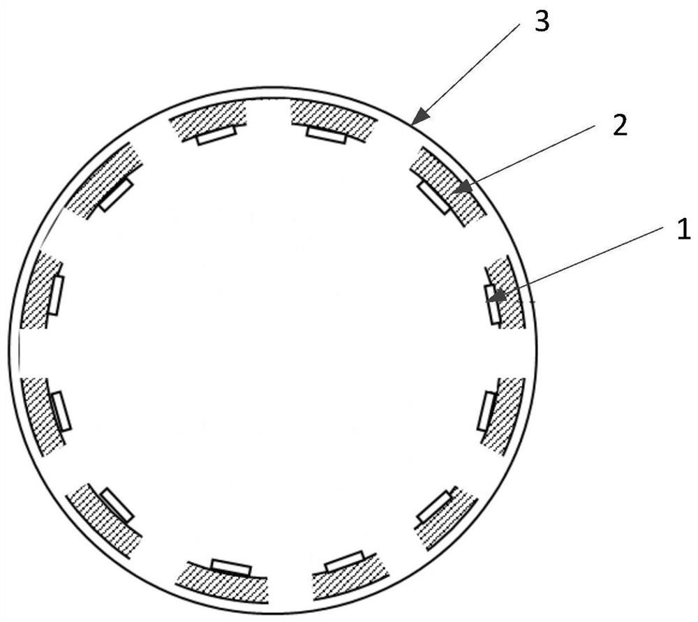
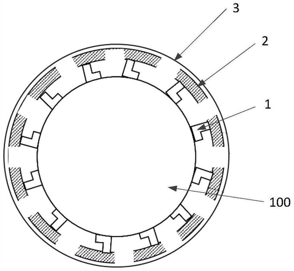
[0003] In order to solve the above-mentioned technical problems, the present invention provides an edge polishing device and a polishing method, which solves the problem of poor wafer edge due to the reduced removal rate caused by the reduced friction between the polishing pad and the wafer during the polishing process

Method used


Image

  • Edge polishing device and polishing method
  • Edge polishing device and polishing method
  • Edge polishing device and polishing method

Examples


Embodiment Construction

[0030] In order to make the purpose, technical solutions and advantages of the embodiments of the present invention more clear, the following will clearly and completely describe the technical solutions of the embodiments of the present invention in conjunction with the drawings of the embodiments of the present invention. Apparently, the described embodiments are some, not all, embodiments of the present invention. All other embodiments obtained by those skilled in the art based on the described embodiments of the present invention belong to the protection scope of the present invention.

[0031] In the description of the present invention, it should be noted that the terms "center", "upper", "lower", "left", "right", "vertical", "horizontal", "inner", "outer" etc. The indicated orientation or positional relationship is based on the orientation or positional relationship shown in the drawings, and is only for the convenience of describing the present invention and simplifying...


PUM


Abstract

The invention relates to an edge polishing device. The edge polishing device comprises a body, a driving component and polishing heads, wherein the body comprises a ring support; the polishing heads are circumferentially fixed to the ring support; the driving component is used for controlling rotation of the body to drive the polishing heads to rotate in order to perform polishing on the edge of awafer; each polishing head comprises a polishing disc; each polishing disc is connected to the ring support through a connecting structure; each connecting structure comprises a sliding rail extending in the circumferential direction of the ring support; each polishing head is movably arranged on the corresponding sliding rail; an elastic displacement sensor for sensing a displacement distance ofeach polishing head on the corresponding sliding rail is arranged between the polishing head and one end of the sliding rail; the driving component comprises a processing unit for acquiring the friction force between the polishing heads and the wafer according to signals of the elastic displacement sensors and sending a control signal; and the driving component further comprises an execution unitfor adjusting the rotation speed of the body according to the control signal in order to adjust the pressure applied to the wafer by the polishing heads to keep the polishing rate constant.

Description

technical field [0001] The invention relates to the technical field of wafer fabrication, in particular to an edge polishing device and a polishing method. Background technique [0002] Semiconductor silicon wafers are the main substrate material for manufacturing VLSI. With the rapid development of the semiconductor industry, the precision requirements for substrate materials are getting higher and higher, especially for the outer surface of silicon wafers. The stricter it is, it is generally necessary to polish the outer surface of the silicon wafer during substrate processing, so as to ensure that there are no defects such as slip lines or epitaxial stacking faults at the edge of the silicon wafer during epitaxy, thereby improving the quality of epitaxial wafers or devices. Yield. The polishing pad that is in contact with the surface of the wafer is made of polyurethane, and its surface has gaps. Due to factors such as particle filling, the shape of the polishing pad wil...

Claims


Application Information

Patent Timeline
Patent Type & Authority Applications(China)
IPC IPC(8): B24B29/02B24B1/00
CPCB24B29/02B24B1/00
Inventor 李昀泽
Owner XIAN ESWIN MATERIAL TECH CO LTD
Learn More