
Variable-rigidity soft finger and control method thereof

A finger and stiffness technology, applied in the field of soft robots, can solve problems such as inability to actively change stiffness, safety and flexibility limitations

Inactive Publication Date: 2020-11-13
ZHEJIANG UNIV OF TECH
View PDF11 Cites 12 Cited by
  • Summary
  • Abstract
  • Description
  • Claims
  • Application Information

AI Technical Summary

Problems solved by technology

[0004] The present invention overcomes the deficiencies that the existing rigid manipulators are soft, cannot actively change the stiffness, and has limited safety and flexibility, and provides a soft finger with variable stiffness, which can actively change the stiffness, and has better security and flexibility. flexibility

Method used


Image

  • Variable-rigidity soft finger and control method thereof
  • Variable-rigidity soft finger and control method thereof
  • Variable-rigidity soft finger and control method thereof

Examples


Embodiment 1

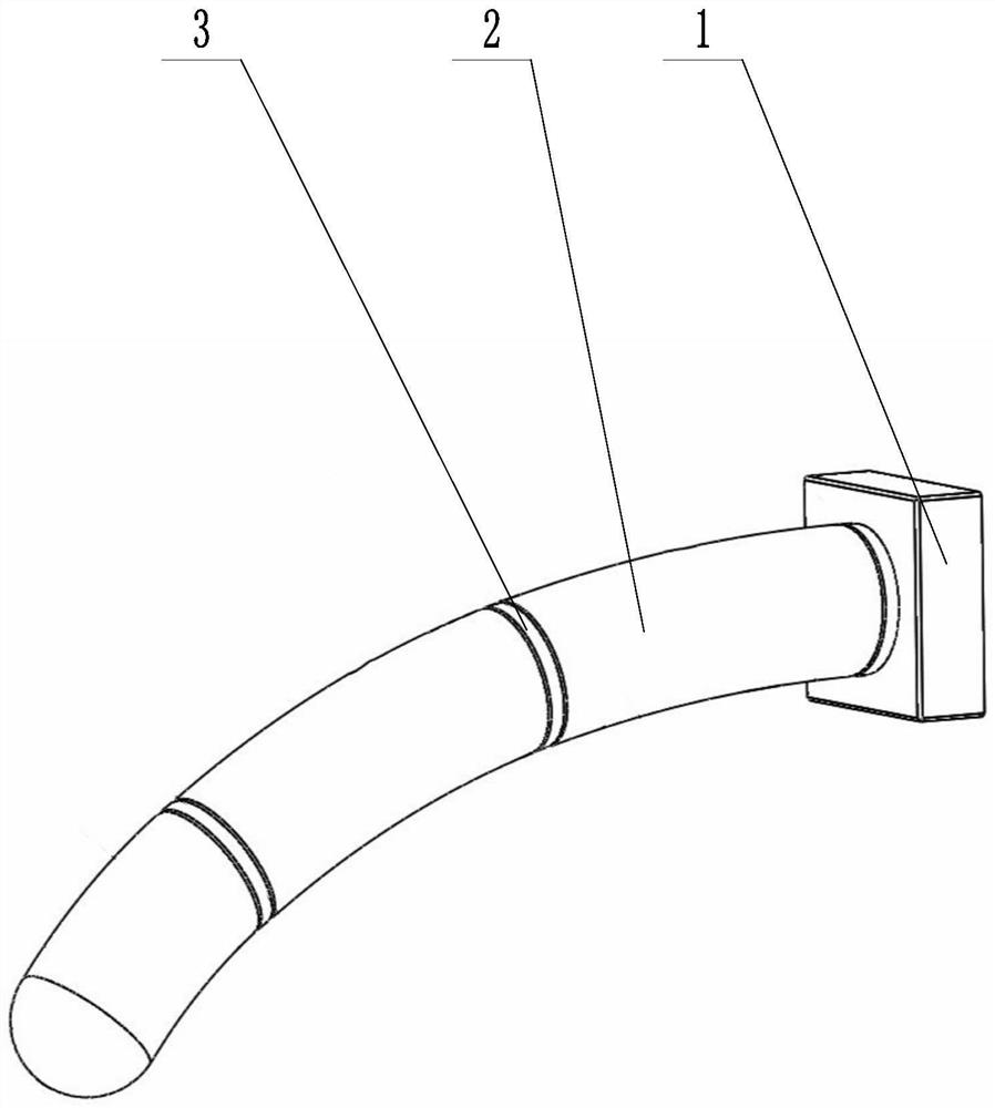
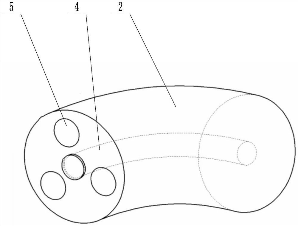
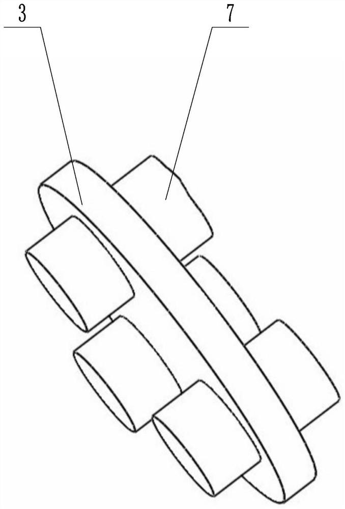
[0033] A soft finger with variable stiffness, such as Figures 1 to 3 As shown, the finger is installed on the base 1, and the base 1 is provided with an air guide hole corresponding to the air channel 5, and the air channel 5 is inserted into the air guide hole. Several bases 1 are connected together to form a mechanical artificial hand. The base 1 corresponds to the position of the palm of a person. High-pressure gas pre-distributed for action is stored on the base 1 . The finger includes a finger section 2 and a knuckle 3. A magneto-rheological fluid channel 4 is arranged in the finger section 2 along the axial direction. The number is three, and the gas pipelines 5 surround the magnetorheological fluid channel 4 at equal intervals. When designing a non-simulation manipulator, several soft fingers can be set to form an array, and adjacent fingers can cooperate. The fingers can be bent in three directions. By cooperating with adjacent fingers, the clamping and grasping ...

Embodiment 2

[0046] Such as Figure 6 Shown, embodiment 2 also has the following features on the basis of embodiment 1:

[0047] A spiral electric wire 9 is connected between adjacent electrodes, the spiral electric wire 9 is arranged around the magnetic flow hose, and the spiral electric wire 9 is flexible. The spiral electric wire 9 is embedded on the finger segment 2, and the finger segment 2 is provided with a channel corresponding to the spiral electric wire 9.

[0048] Due to the difference in the amount of gas charged between the various air pipelines 5, the degree of bending of the fingers is also not certain. The magnetic field between the two electrodes must be the strongest when the two are connected in a straight line, and the corresponding finger stiffness will be higher. Due to the bending of the finger, the magnetic lines of force corresponding to the magnetorheological fluid in the corresponding magnetic fluid hose 6 are relatively weak. In order to avoid this situation,...


PUM


Abstract

The invention discloses a variable-rigidity soft finger and a control method thereof, and aims to solve the defects that a rigid manipulator in the prior art is soft, cannot actively change rigidity,and is limited in safety and flexibility. The variable-rigidity soft finger comprises finger sections and finger knuckles, wherein a magnetorheological fluid channel is arranged in each finger sectionin the axial direction; each finger section is equipped with a gas path pipeline around the corresponding magnetorheological fluid channel; a magnetic fluid hose is embedded into each magnetorheological fluid channel; magnetorheological fluid is arranged in each magnetic fluid hose; the finger sections and the finger knuckles are arranged at intervals; corresponding through holes are formed in positions, which correspond to the gas path pipelines, of the finger knuckles; electrodes communicate on the finger knuckles; the electrodes form magnetic fields on the finger sections; and directions of magnetic fields passed by adjacent finger sections are opposite. The variable-rigidity soft finger integrates advantages of a rigid finger and a flexible finger, further can keep relatively great rigidity besides grabbing and positioning of a soft fragile object, and can output relatively great grabbing force.

Description

technical field [0001] The invention relates to the field of soft robots, more specifically, it relates to a soft finger with variable stiffness. Background technique [0002] At present, traditional rigid manipulators have been widely accumulated and used in many fields such as industry and medical treatment. However, with the continuous improvement of environmental requirements, in some special application scenarios, such as the grasping of soft and fragile objects, the grasping and positioning assembly of precision parts, and the operation in narrow spaces, the traditional rigid manipulator encounters obstacles due to its fixed rigidity. Objects cannot be actively deformed, their safety and flexibility are greatly limited, and they cannot perform specific tasks well. With the development of 3D printing technology and new smart materials, research on soft hands has gradually begun to rise, and its good flexibility and flexibility can well make up for the lack of rigid man...

Claims


Application Information

Patent Timeline
IPC IPC(8): B25J9/10B25J9/14B25J15/00
CPCB25J9/10B25J9/14B25J15/00
Inventor 马小龙韦威孟海良鲍官军
Owner ZHEJIANG UNIV OF TECH
Learn More