
Mechanical flattening device for plastic

A technology of plastic machinery and equipment, which is applied in the field of plastic mechanical feeding equipment, can solve the problems of chains not running smoothly, affecting the feeding effect, and chain elongation, so as to eliminate the phenomenon of chain swinging, uniform and reliable feeding effect, and work The effect of position stabilization

Pending Publication Date: 2020-11-13
南安建成机械有限公司
View PDF0 Cites 0 Cited by
  • Summary
  • Abstract
  • Description
  • Claims
  • Application Information

AI Technical Summary

Problems solved by technology

[0003] In the chain tensioning process of existing equipment, there will be two situations: too tight and too loose. If the tension is too tight, it is easy to elongate the chain and reduce the service life of the chain. The wheel is tilted, the chain cannot run smoothly, and the sprocket and chain are easy to wear. If the tension is too loose, firstly, if the tension is too loose, the running process of the chain will be noisy, and secondly, the beating rod installed on the chain will be thrown back and forth. Phenomenon, unable to install the established trajectory operation, thus affecting the effect of beating
[0004] The distance between the existing punching rod and the hot needle is fixed, and the fixed distance leads to a fixed amount of punching that can be allowed. If the quantity is large, the space is too large when the quantity is small, which will affect the punching effect. If the quantity is small In the case of a large number, it cannot be done

Method used


Image

  • Mechanical flattening device for plastic
  • Mechanical flattening device for plastic
  • Mechanical flattening device for plastic

Examples


Embodiment Construction

[0030] Example embodiments will now be described more fully with reference to the accompanying drawings. Example embodiments may, however, be embodied in many forms and should not be construed as limited to the examples set forth herein; Fully conveyed to those skilled in the art. The drawings are merely schematic illustrations of the present disclosure and are not necessarily drawn to scale. The same reference numerals in the drawings denote the same or similar parts, and thus repeated descriptions thereof will be omitted.

[0031] Furthermore, the described features, structures, or characteristics may be combined in any suitable manner in one or more example embodiments. In the following description, numerous specific details are provided in order to give a thorough understanding of example embodiments of the present disclosure. However, those skilled in the art will appreciate that the technical solutions of the present disclosure may be practiced without one or more of ...


PUM


Abstract

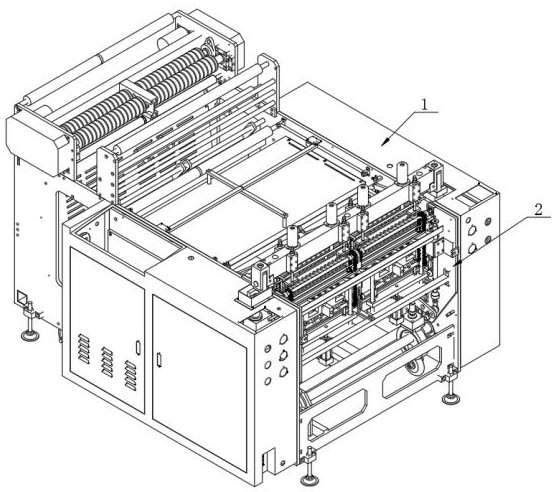
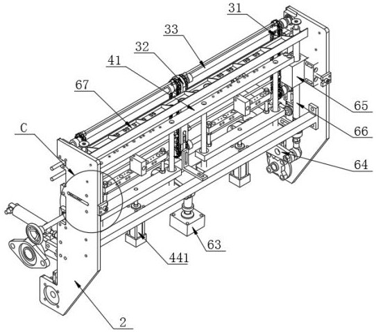
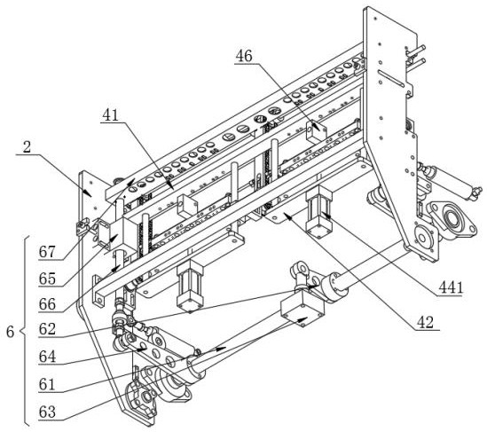
The invention discloses a mechanical flattening device for plastic, and specifically relates to the technical field of plastic bag production devices. The mechanical flattening device for the plasticcomprises a device body, flattening side plates are fixedly installed on two sides of the interior of the device body, and a flattening mechanism is arranged between the two flattening side plates. The flattening mechanism comprises two side groove plates, one sides of the two side groove plates are fixedly installed on the side walls of the two flattening side plates respectively, a middle grooveplate is arranged in the middle between the two side groove plates, main shafts are arranged on the upper portion and the lower portion between the two side groove plates, two ends of the two main shafts are rotatably connected with the side walls of the two flattening side plates respectively, and the two ends and the middle portions of the two main shafts are rotatably connected with the upperportions and the lower portions of the two side groove plates and the middle groove plate respectively. According to the mechanical flattening device for the plastic, by making chains operate stably in side chain grooves and middle chain grooves, the chains will not swing, so the working positions of flattening rods are stable, and the flattening effect is uniform and reliable.

Description

technical field [0001] The invention relates to the technical field of plastic bag production equipment, more specifically, the invention relates to a plastic mechanical beating equipment. Background technique [0002] Plastic bag is a bag made of plastic (commonly used plastics include polypropylene, polyester, nylon, etc.) as the main raw material. It is an indispensable item in people's daily life and is often used to hold other items. The advantages of extremely light, large capacity, and easy storage are widely used. In the production process of plastic bags, the plastic bags need to be cut and separated, and the plastic bags need to be flattened before cutting, so that the cut plastic bags are relatively flat , without folding. [0003] In the chain tensioning process of existing equipment, there will be two situations: too tight and too loose. If the tension is too tight, it is easy to elongate the chain and reduce the service life of the chain. The wheel is tilted,...

Claims


Application Information

Patent Timeline
Patent Type & Authority Applications(China)
IPC IPC(8): B31B70/04B31B70/74
CPCB31B70/04B31B70/74
Inventor 潘丽成
Owner 南安建成机械有限公司
Learn More