Adjustable soil shovel conveyor

A transporter and adjustable technology, applied in the direction of mechanically driven excavators/dredgers, etc., can solve the problems of vehicle operators' safety threats and inability to slide down by themselves

Inactive Publication Date: 2020-11-13
刘培泉
View PDF0 Cites 2 Cited by
  • Summary
  • Abstract
  • Description
  • Claims
  • Application Information

AI Technical Summary

Problems solved by technology

[0002] The earth shovel transporter plays an irreplaceable role in construction and other aspects, especially in the application of shoveling soil, with its own bucket structure, it can realize the shoveling and transportation of sand and soil, but the traditional shovel transporter is not suitable for pushing and shoveling sand and soil. There is an obvious disadvantage in the process, that is, the sand will be transformed into a compact stacked state due to the gravity factor after a long per

Method used


Image

  • Adjustable soil shovel conveyor
  • Adjustable soil shovel conveyor
  • Adjustable soil shovel conveyor

Examples


Embodiment

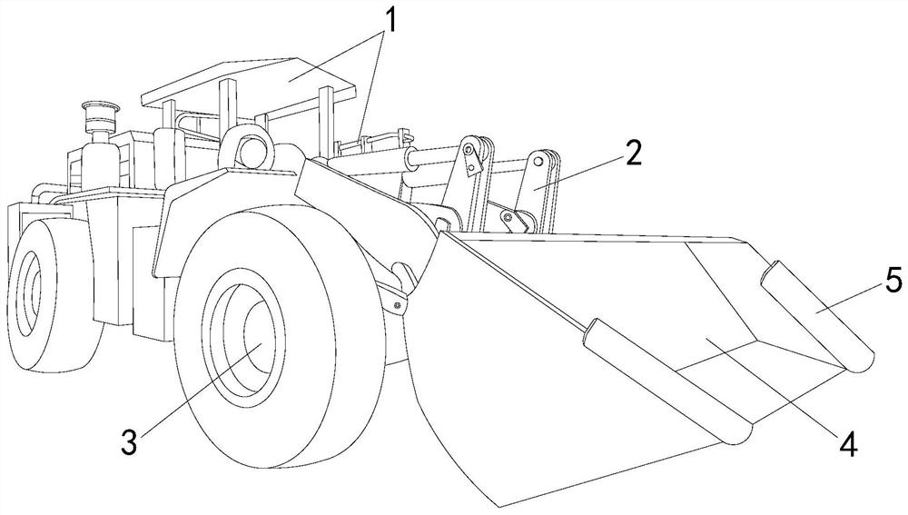
[0023] see figure 1 , the present invention provides an adjustable earth shovel transporter, the structure of which includes: frame 1, push rod arm 2, drive wheel 3, bucket 4, soil loosening mechanism 5, the front end of the frame 1 is connected to the push rod arm 2 And its bottom is provided with driving wheel 3 and is connected with it, bucket 4 is located at one end of push rod arm 2 and its both sides are provided with soil loosening mechanism 5, and frame 1 is the vehicle body structure of transporter, includes the vehicle body frame structure and the shelter of the top at the same time structure and power supply structure, the push rod arm 2 is the connection carrier between the frame 1 and the bucket 4, and is also a power component used to control the forward and backward retraction of the bucket 4. The height can realize the action of pushing and shoveling sand and soil and make the bucket 4 turn over at a specific angle by means of a certain angle. The driving whee...

Embodiment 2

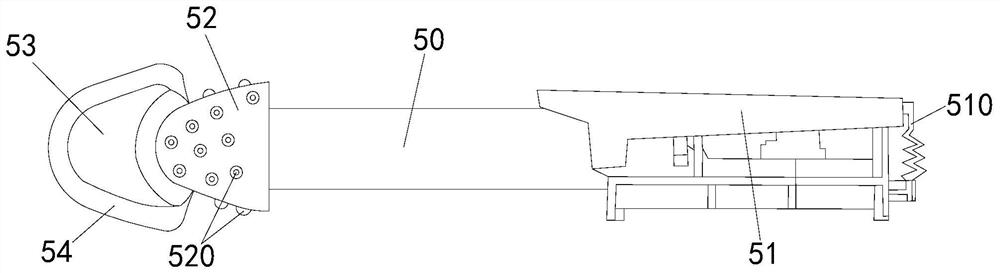
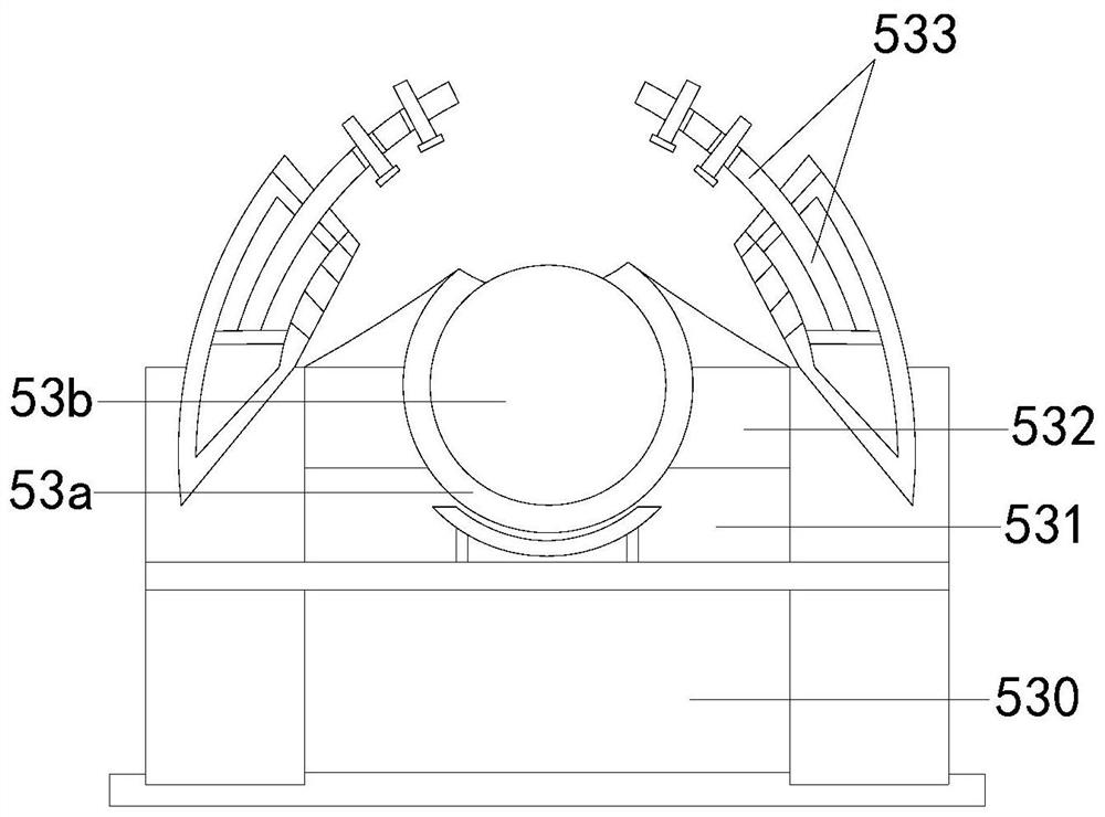
[0029] The description of the second embodiment drawn in conjunction with the first embodiment, combined with figure 2 , image 3 and Figure 4 The two ends of the slide rod 50 are respectively connected to the piston rod 51 and the drill bit 52, the top position of the drill bit 52 is connected to the push head 53 and a vibration bag 54 is arranged on the outside, the top of the socket 530 is connected to the ball seat 531, and the ball seat 531 is two A hook contactor 532 is provided on the side and a drill ring 533 is correspondingly provided above it, and a pressing block 5321 is provided on the base 5320, and a pressing block 5321 and a slot 5325 opened on the surface of the base 5320 are correspondingly provided with an extrusion Cone 5324 and extruding cone 5324 are connected to pressing frame 5322 through hook spring 5323. When bucket 4 just enters the range of sand and soil stacking, the drill ring 533 is driven by slide rod 50 to rotate at high speed to destroy the...


PUM


Abstract

The invention discloses an adjustable soil shovel conveyor which structurally includes a machine frame, a push rod arm, a driving wheel, a shovel bucket, and soil loosening mechanisms. The front end of the machine frame is connected with the push rod arm, and the driving wheel is arranged at and is connected with the bottom of the machine frame. The shovel bucket is located at one end of the pushrod arm, and the soil loosening mechanisms are arranged on the two sides of the shovel bucket. The adjustable soil shovel conveyor has the beneficial effects that first, a drill ring in the mechanismis used to be in contact with sandy soil during high-speed rotation and rub against with the sandy soil to destroy the stacking state of the sandy soil so as to enable the sandy soil to turn into a loose state; and second, a squeeze cone is used to break the pressure tension of an air pressure ball to trigger the high-pressure ejection of internal air to disperse the sandy soil covering parts, thesandy soil slide down naturally through the cooperation the air and the parts, the conveyor is prevented from going deep into a sandy soil coverage area, and the risk of being buried is minimized.

Description

technical field [0001] The invention relates to the field of construction, in particular to an adjustable earth-shoveling machine. Background technique [0002] The earth shovel transporter plays an irreplaceable role in construction and other aspects, especially in the application of shoveling soil, with its own bucket structure, it can realize the shoveling and transportation of sand and soil, but the traditional shovel transporter is not suitable for pushing and shoveling sand and soil. There is an obvious disadvantage in the process, that is, the sand will be transformed into a compact stacked state due to the gravity factor after a long period of loose stacking. It cannot slide down by itself, so it is easy to push the shovel. In order to loosen the sand and soil to facilitate the operation, it is necessary to operate the vehicle to push forward and then quickly retreat. In the process, the sand will fall quickly under the influence of external force, but it will also p...

Claims


Application Information

Patent Timeline
IPC IPC(8): E02F3/28E02F3/36
CPCE02F3/28E02F3/36
Inventor 刘培泉
Owner 刘培泉
Why Eureka
Try Eureka