Hydraulic pipeline arrangement structure

A technology for arranging structures and hydraulic pipelines, applied in the field of hydraulic systems, can solve the problems of inconvenient operation of maintenance personnel, disordered outlet pipelines, and easy interference of hydraulic control valves, so as to improve maintenance efficiency, maintenance quality, and maintenance convenience. And the effect of high security, easy to manage design

Pending Publication Date: 2020-11-13
WISDRI ENG & RES INC LTD
View PDF0 Cites 0 Cited by
  • Summary
  • Abstract
  • Description
  • Claims
  • Application Information

AI Technical Summary

Problems solved by technology

[0003] However, after on-site investigation, it was found that when the construction unit laid out the hydraulic pipelines, the outlet pipelines of the hydraulic valve table did not have a good layout method. The valves are easy to interfere with each other, and it is not easy to find and repair the fault point of the maintenance pipeline; some projects fix these outlet pipelines by setting pipeline brackets on the adjacent structural wall, resulting in no maintenance space on the side of the structural wall, only from the valve Maintenance at the side of the platform or squatting under the outlet pipe, the maintenance space is small, the maintenance personnel are inconvenient to operate and even need to step over the hydraulic valve platform and step on the outlet pipeline for maintenance, not only the maintenance efficiency is low, but also the operation safety It cannot be guaranteed; and generally there are many outlet pipes arranged side by side, and there are relatively many hydraulic control valves, and the gap between the valves is very small, resulting in difficult maintenance and serious problems

Method used


Image

  • Hydraulic pipeline arrangement structure
  • Hydraulic pipeline arrangement structure
  • Hydraulic pipeline arrangement structure

Examples


Embodiment Construction

[0023] The following clearly and completely describes the technical solutions in the embodiments of the present invention. Obviously, the described embodiments are only some of the embodiments of the present invention, but not all of them. Based on the embodiments of the present invention, all other embodiments obtained by persons of ordinary skill in the art without making creative efforts belong to the protection scope of the present invention.

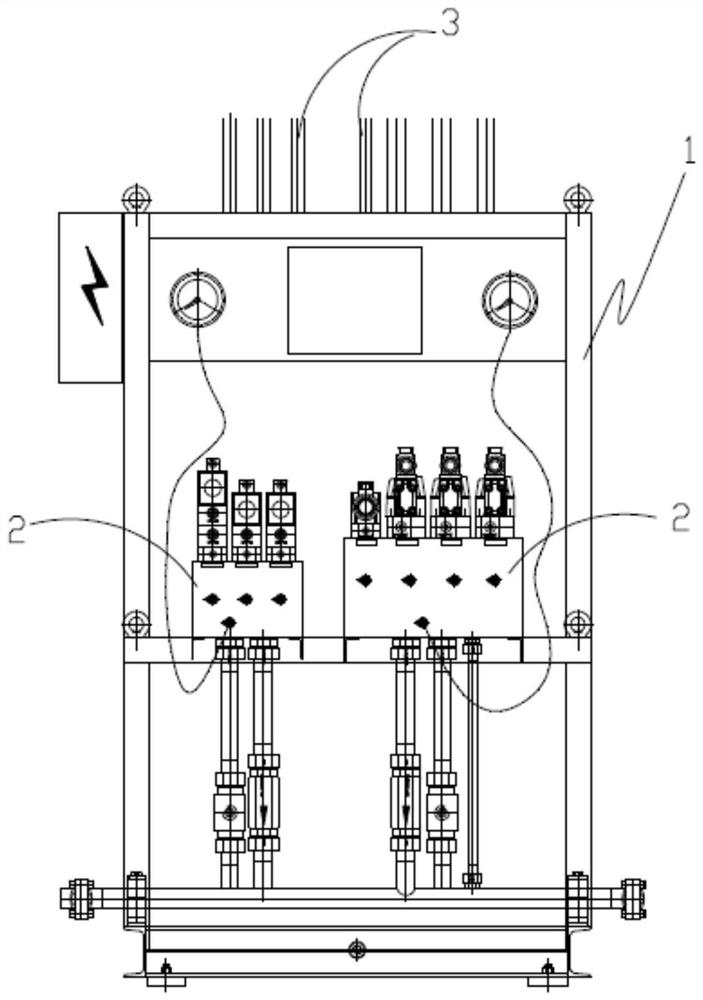
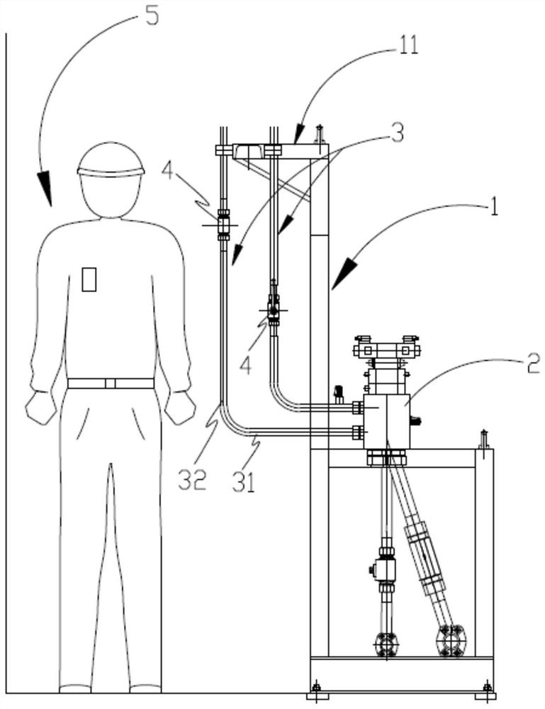
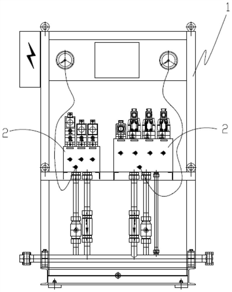
[0024] Such as Figure 1-Figure 4 , the embodiment of the present invention provides a hydraulic pipeline layout structure, including a mounting frame 1, a hydraulic valve table 2 connected to a hydraulic station is arranged on one side of the mounting frame 1, and a hydraulic valve table 2 connected to a hydraulic station is arranged on the other side of the mounting frame 1. Pipeline support 11, the hydraulic outlet pipe 3 of the hydraulic valve table 2 passes through the installation frame 1 and pipes from the side where the pipe...


PUM


Abstract

The invention relates to a hydraulic pipeline arrangement structure. The hydraulic pipeline arrangement structure comprises an installation frame, wherein a hydraulic valve stand connected with a hydraulic station is arranged on one side of the installation frame, a pipeline support is arranged on the other side of the installation frame, hydraulic outlet pipes of the hydraulic valve stand penetrate through the installation frame, are distributed from the side where the pipeline support is located and are connected with the pipeline support, and hydraulic control valves are arranged on the hydraulic outlet pipes on the side where the pipeline support is located. By arranging the installation frame and arranging the pipeline support on the installation frame, the hydraulic outlet pipes of the hydraulic valve stand can be designed to be distributed on the back face of the installation frame, on the one hand, the situation that the hydraulic outlet pipes are arranged disorderly can be avoided, the relative positions of the hydraulic outlet pipes and the relative positions of the hydraulic control valves are easy to manage and design, and a maintainer can conveniently find and maintaina pipeline fault point; and on the other hand, maintenance personnel can perform maintenance on the back face of the installation frame, enough maintenance space is achieved, maintenance convenienceand safety are high, and the maintenance efficiency and the maintenance quality of the hydraulic pipeline can be remarkably improved.

Description

technical field [0001] The invention belongs to the technical field of hydraulic systems, and in particular relates to a hydraulic pipeline layout structure. Background technique [0002] Due to its high efficiency, convenient and flexible layout, fast response, and easy automation, the hydraulic system is widely used in the blast furnace ironmaking process and is an important facility selected by many iron and steel enterprises. The hydraulic pipeline is an important facility for transmitting hydraulic power to the driving equipment. There are many ball valves, hoses, joints, etc. on the pipeline; during use, the hydraulic pipeline sometimes has some faults and needs to be repaired. Taking the furnace front hydraulic system in the blast furnace hydraulic system as an example, the furnace front hydraulic system provides working power for the three major equipment of the blast furnace mud gun, tap hole machine, and swing chute. When the hydraulic pipeline fails, the furnace f...

Claims


Application Information

Patent Timeline
Patent Type & Authority Applications(China)
IPC IPC(8): F15B13/02F15B13/04
CPCF15B13/02F15B13/04
Inventor 危丹锋程文芳牟丹王文聪金文浩
Owner WISDRI ENG & RES INC LTD
Why Eureka
Try Eureka