An anti-clogging heat exchanger

A heat exchanger and anti-clogging technology, which is applied to indirect heat exchangers, heat exchanger types, heat exchanger shells, etc. Easy to block and other problems, to achieve the effect of easy cleaning and maintenance, low maintenance cost, and improve heat exchange efficiency

Active Publication Date: 2022-08-02
青岛康景辉环境科技集团有限公司
View PDF10 Cites 0 Cited by
  • Summary
  • Abstract
  • Description
  • Claims
  • Application Information

AI Technical Summary

Problems solved by technology

[0004] The present invention aims at the problem that the inside of the heat exchanger is easy to be blocked and the heat exchange efficiency is low; and the problem that the filter cannot be disassembled online; Due to the problem of cleaning and maintenance, an anti-clogging heat exchanger with online detachable filter tube is designed

Method used


Image

  • An anti-clogging heat exchanger
  • An anti-clogging heat exchanger
  • An anti-clogging heat exchanger

Examples


Embodiment 1

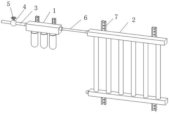
[0035] An anti-clogging heat exchanger such as figure 1As shown, it includes a tertiary filter 1 and a heat exchanger body 2. The left end of the tertiary filter 1 is connected with a liquid inlet metal pipe 3. The liquid inlet metal pipe 3 is provided with a control valve 4, and the top of the control valve 4 is provided with a flow rate Adjust the switch 5, the right end of the tertiary filter 1 is connected with a liquid outlet metal pipe 6, and the liquid outlet metal pipe 6 is communicated with the heat exchanger body 2; the rear side walls of the tertiary filter 1 and the heat exchanger body 2 are fixed There is an installation frame piece 7, the installation frame piece 7 is provided with a fixing hole, and the installation frame piece 7 is arranged to facilitate fixing the tertiary filter 1 and the heat exchanger body 2 on the wall or other racks.

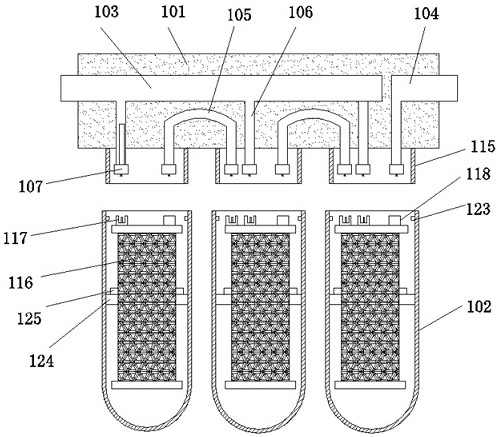
[0036] Among them, such as Figure 2-6 As shown, the tertiary filter 1 includes a top seat 101 and a filter tube 102. Th...

Embodiment 2

[0041] On the basis of Example 1, as Figure 8 As shown, the heat exchanger body 2 includes a liquid inlet manifold 201 and a liquid outlet manifold 202. A number of guide pipes 203 arranged at equal intervals are communicated between the liquid inlet manifold 201 and the liquid outlet manifold 202. The liquid inlet manifold A liquid inlet connector 204 is installed on the left side wall of the pipe 201, and a liquid outlet connector 205 is installed on the left side wall of the liquid outlet manifold 202; the downstream of the liquid outlet connector 205 is connected with a recovery container 207 through a liquid outlet hose 206, The side wall of the recovery container 207 is connected with the recovery pipe 209 and the backflushing pipe 208. The liquid outlet end of the backflushing pipe 208 is connected with three backflushing branch pipes 210, and the bottom ends of the three backflushing branch pipes 210 respectively penetrate the top seat 101 and extend into To the inter...

Embodiment 3

[0044] On the basis of Example 2, as Figure 9 and Figure 10 As shown, the heat exchanger body 2 includes a liquid inlet manifold 201 and a liquid outlet manifold 202, and between the liquid inlet manifold 201 and the liquid outlet manifold 202 are several guide pipes 203 arranged at equal intervals; The outer wall of the 203 is provided with an annular installation groove 215, the outer wall of the annular installation groove 215 is sleeved with a pair of arc-shaped pieces 216, and the pair of arc-shaped pieces 216 are fixed and installed by bolts, and the outer walls of the pair of arc-shaped pieces 216 are all integrated. The heat dissipation fins 217 are fixed.

[0045] When this embodiment is used, a pair of bolts can be used to fix the arc-shaped sheet 216 to the outer wall of the annular mounting groove 215. The heat-dissipating fins 217 integrally fixed to the outer wall of the arc-shaped sheet 216 can increase the heat dissipation area, thereby improving the heat ex...


PUM


Abstract

The invention relates to the technical field of heat exchanger production, in particular to an anti-clogging heat exchanger, comprising a three-stage filter and a heat exchanger body. The left end of the three-stage filter is connected with a liquid inlet metal pipe, and the liquid inlet metal pipe is provided There is a control valve, the top of the control valve is provided with a flow adjustment switch, the right end of the three-stage filter is connected with a liquid outlet metal pipe, and the liquid outlet metal pipe is communicated with the heat exchanger body; the present invention does not need to consider the three-stage filter and heat exchange. Whether the filter is working, the filter tube on the filter can be disassembled online, and no liquid will flow out during the installation and replacement process, and the sealing performance is good. At the same time, the disassembly and replacement operation is very simple and flexible, and the maintenance cost is low; The backwash function can be used to flush out the impurities attached to the outer wall of the filter element, which can prevent the filter element from being blocked; at the same time, the heat dissipation fins can increase the heat dissipation area, improve the heat exchange efficiency, and can also be removed for cleaning, avoiding the dead angle of hygiene, It is convenient for daily cleaning and maintenance.

Description

technical field [0001] The invention relates to the technical field of heat exchanger production, in particular to an anti-clogging heat exchanger capable of online disassembly and assembly of filter tubes. Background technique [0002] Heat exchanger is an energy-saving device that realizes heat transfer between materials between two or more fluids at different temperatures. It transfers heat from a fluid with a higher temperature to a fluid with a lower temperature, so that the fluid temperature reaches the The specified indicators to meet the needs of process conditions, but also one of the main equipment to improve energy efficiency. Heat exchangers play an important role in chemical, petroleum, power, food and many other industrial productions. In chemical production, heat exchangers can be used as heaters, coolers, condensers, evaporators and reboilers, etc., and are widely used. . [0003] For example, the utility model with the patent number of 201721230596.X is th...

Claims


Application Information

Patent Timeline
Patent Type & Authority Patents(China)
IPC IPC(8): F28D1/053F28F9/26F28F19/01F28F1/20B01D29/11B01D29/56
CPCF28D1/05333F28F9/26F28F19/01F28F1/20B01D29/11B01D29/56
Inventor 黄书安舒亮亮
Owner 青岛康景辉环境科技集团有限公司
Why Eureka
Try Eureka