

Heavy truck fuel tank oil shaking characteristic test device and test method
A characteristic testing and fuel tank technology, which is applied in the field of testing devices for fuel tank oil sloshing characteristics of heavy truck vehicles, can solve the problems of structural improvement of fuel tanks or unsatisfactory research and development results, and difficulty in simulating the movement of fuel tanks in a realistic manner, so as to avoid fatigue damage. , the effect of reducing friction
- Summary
- Abstract
- Description
- Claims
- Application Information
AI Technical Summary
Problems solved by technology
Method used
Image

Examples
Embodiment 1
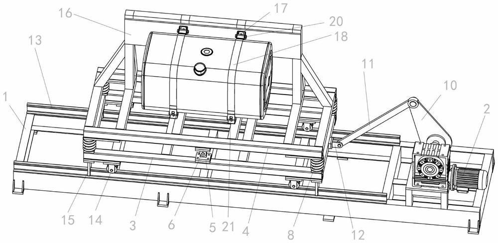
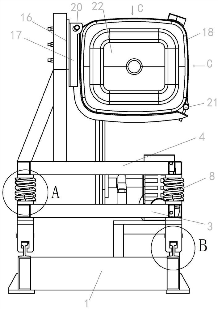
[0040] refer to Figure 1 to Figure 11 As shown, a heavy-duty vehicle fuel tank oil sloshing characteristic test device includes a bench test platform, and the bench test platform includes a test piece connection unit and a power unit, and the power unit includes a chassis 1 and a driver 2. The chassis 1 is fixed on the ground, and the driver 2 is installed on the chassis 1. The driver 2 includes a worm gear reducer and a bearing seat for installing the main shaft. The output end of the driver 2 is provided with a reciprocating transmission mechanism. The test piece connection unit includes a sliding bracket 3, a fixed bracket 4 and a fuel tank connector. The sliding bracket 3 is slidably arranged on the bottom frame 1. The sliding bracket 3 is movably connected with the reciprocating transmission mechanism. The sliding bracket 3 drives the reciprocating Realize left and right reciprocating movement under the effect of transmission mechanism, the middle position of the front a...
Embodiment 2
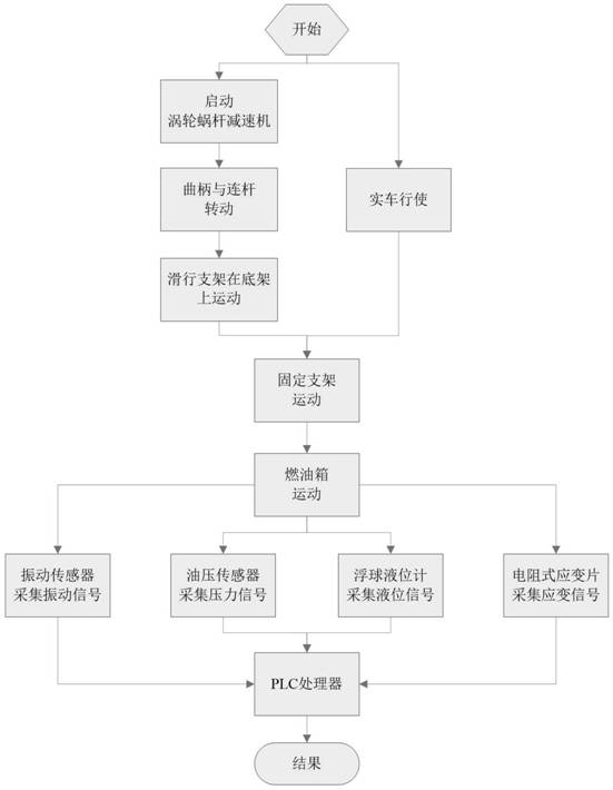
[0057] A test method for a test device for the sloshing characteristics of a fuel tank of a heavy truck vehicle, comprising the following steps:
[0058] A. First arrange the vibration sensor on the fuel tank bracket 17 and the strap 18, arrange the resistive strain gauge on the anti-wave plate 19 and the fuel tank end cap 22, arrange the oil pressure sensor on the fuel tank end cap, and arrange the fuel tank end cap 22 and the A float level gauge is arranged on the wall of the fuel tank between the corrugated plates 19;
[0059] B. Fix the fuel tank on the support plate 16 of the fixed bracket 9 through the fuel tank bracket 17, the strap 18, the upper pin 20 and the lower pin 21, the strap 18 is hooped on the fuel tank outside the wave plate 19 and It coincides with the position of the anti-wave plate 19;
[0060] C. Then start the driver 2, drive the connecting rod 11 to move back and forth through the crank 10, and at the same time drive the sliding bracket 3 to realize t...
PUM
 Abstract
Description
Claims
Application Information