
Glue wiping and needle correcting mechanism

A technology of glue-wiping and pin calibration, which is applied in spraying devices, coatings, and devices for coating liquid on the surface, etc. It can solve the problems of glue dislocation and residual glue, etc., achieve accurate positioning and correction, solve residual glue, The effect of solving dispensing misalignment

Pending Publication Date: 2020-11-17
SUZHOU RS TECH
View PDF0 Cites 0 Cited by
  • Summary
  • Abstract
  • Description
  • Claims
  • Application Information

AI Technical Summary

Problems solved by technology

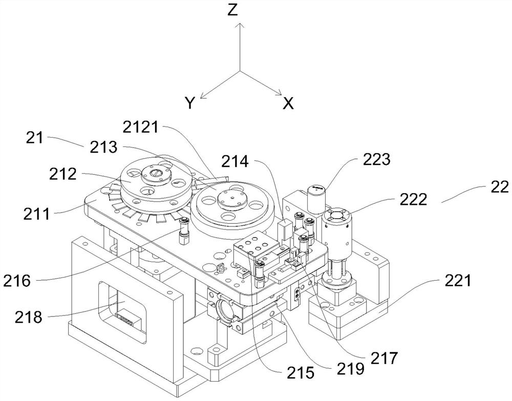
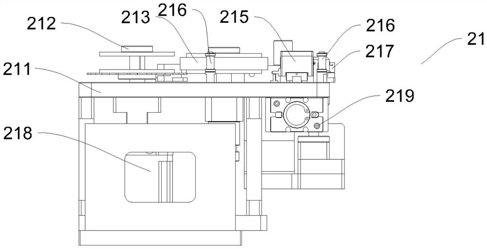
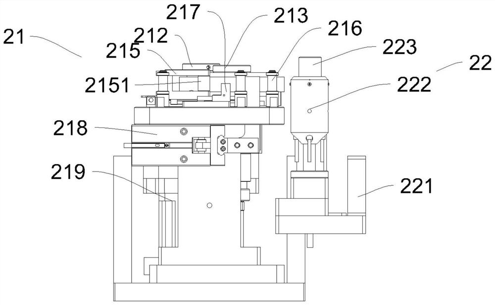
[0004] Aiming at the deficiencies in the prior art, the object of the present invention is to provide a glue-wiping and needle-calibrating mechanism, which can make the tape and the needle closely contact with the glue-wiping assembly, and wipe off the glue on the surface of the needle, thereby Solve the problem of residual glue, and accurately position and correct the dispensing needle through the calibration needle assembly, thus solving the dislocation phenomenon of dispensing

Method used


Image

  • Glue wiping and needle correcting mechanism
  • Glue wiping and needle correcting mechanism
  • Glue wiping and needle correcting mechanism

Examples


Embodiment Construction

[0029] The present invention will be further described in detail below in conjunction with the accompanying drawings, and the aforementioned and other objects, features, aspects and advantages of the present invention will become more apparent, so that those skilled in the art can implement them with reference to the description. In the drawings, the shapes and dimensions may be exaggerated for clarity, and the same reference numerals will be used throughout to designate the same or like parts. In the following description, terms such as center, thickness, height, length, front, back, rear, left, right, top, bottom, upper, lower, etc. are based on orientations or positional relationships shown in the drawings. In particular, "height" corresponds to the dimension from top to bottom, "width" corresponds to the dimension from left to right, and "depth" corresponds to the dimension from front to back. These relative terms are for convenience of description and are generally not in...


PUM


Abstract

The invention discloses a glue wiping and needle correcting mechanism which comprises a glue wiping assembly and a needle correcting assembly located beside the glue wiping assembly; wherein the gluewiping assembly comprises a supporting base, a first roller located above the supporting base, a second roller arranged beside the first roller, and at least one clamping block arranged above the supporting base, and a middle transmission structure including a plurality of transmission rollers, and the clamping blocks are arranged in a face-to-face mode. The glue wiping and needle correcting mechanism has the beneficial effects that, through the glue wiping assembly, a material belt can be in close contact with a needle, and glue on the surface of the needle is wiped up, so that the problem ofresidual glue is solved; a dispensing needle is accurately located and corrected through the needle correcting assembly, so that the phenomenon of dispensing dislocation is avoided.

Description

technical field [0001] The invention relates to the field of mechanical automation. More specifically, the present invention relates to a rubber calibration mechanism. Background technique [0002] The glue valve is composed of valve body, cylinder, glue outlet body, piston rod and corrosion-resistant small parts. The cylinder and valve body are separated by corrosion-resistant gaskets and sealing rings to prevent glue from entering the cylinder in the state of glue outlet. The valve in the valve body is fixed on the piston rod, and the opening and closing of the glue can be achieved by the switch of the valve. The back-suction glue valve adopts the back-suction glue-off structure, so that the glue can be sucked back and cut off instantly at the same time when the glue is stopped, reducing the residual glue on the remaining needle, so that there will be no stringing or dripping after dispensing. The rubber valve body is anodized by imported aluminum alloy, the gasket and s...

Claims


Application Information

Patent Timeline
Patent Type & Authority Applications(China)
IPC IPC(8): B05C5/02B05B15/50B05C11/00
CPCB05C5/02B05C11/00B05B15/50
Inventor 缪磊袁文卿周永昌吴建武徐雨舟
Owner SUZHOU RS TECH
Learn More