A kind of construction steel bar cutting device

A truncation device, a technology for building steel bars, applied in cleaning methods and utensils, chemical instruments and methods, and smoke and dust removal, etc., can solve problems such as low efficiency, achieve the effects of convenient use, avoid artificial movement, and improve truncation efficiency

Active Publication Date: 2022-05-06
河南航天建筑工程有限公司
View PDF7 Cites 0 Cited by
  • Summary
  • Abstract
  • Description
  • Claims
  • Application Information

AI Technical Summary

Problems solved by technology

[0002] Steel bar refers to the steel used for reinforced concrete and prestressed reinforced concrete, whose cross section is circular, sometimes square with rounded corners; including smooth round steel bar, ribbed steel bar, twisted steel bar; steel bar mainly bears tensile stress in concrete Deformed steel bars have greater bonding capacity with concrete due to the action of ribs, so they can better withstand external forces; steel bars are widely used in various building structures; especially large, heavy, light thin-walled and high-rise building structures At present, the truncation of building steel bars is usually carried out manually, which is not only inefficient, but also requires two or more people to cooperate during the stage process. One person takes the steel bar, and the other person measures it. After the measurement, the truncation is performed; The steel bars need to be artificially placed elsewhere in order to perform secondary truncation

Method used


Image

  • A kind of construction steel bar cutting device
  • A kind of construction steel bar cutting device
  • A kind of construction steel bar cutting device

Examples


Embodiment Construction

[0025] The construction steel bar cutting device of the present invention will be described in more detail below in conjunction with the accompanying drawings and through specific embodiments.

[0026] In describing the present invention, it should be understood that the terms "upper", "lower", "front", "rear", "left", "right", "top", "bottom", "inner", " The orientation or positional relationship indicated by "outside", etc. is based on the orientation or positional relationship shown in the drawings, and is only for the convenience of describing the present invention and simplifying the description, rather than indicating or implying that the referred device or element must have a specific orientation, so as to Specific orientation configurations and operations, therefore, are not to be construed as limitations on the invention.

[0027] The present invention will be further described below in conjunction with the accompanying drawings.

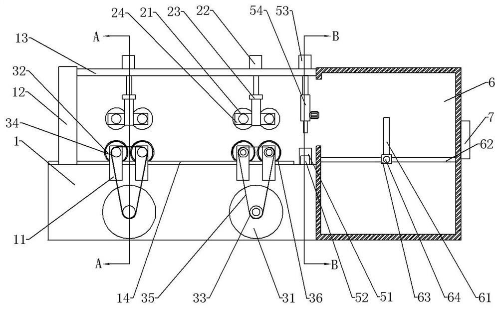
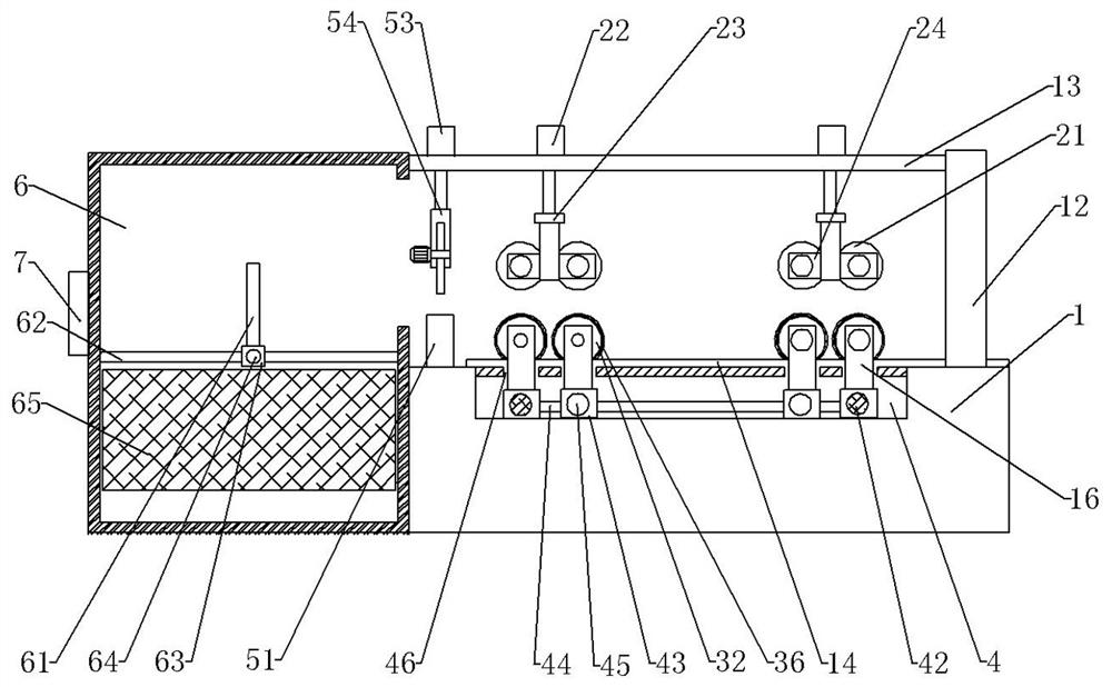
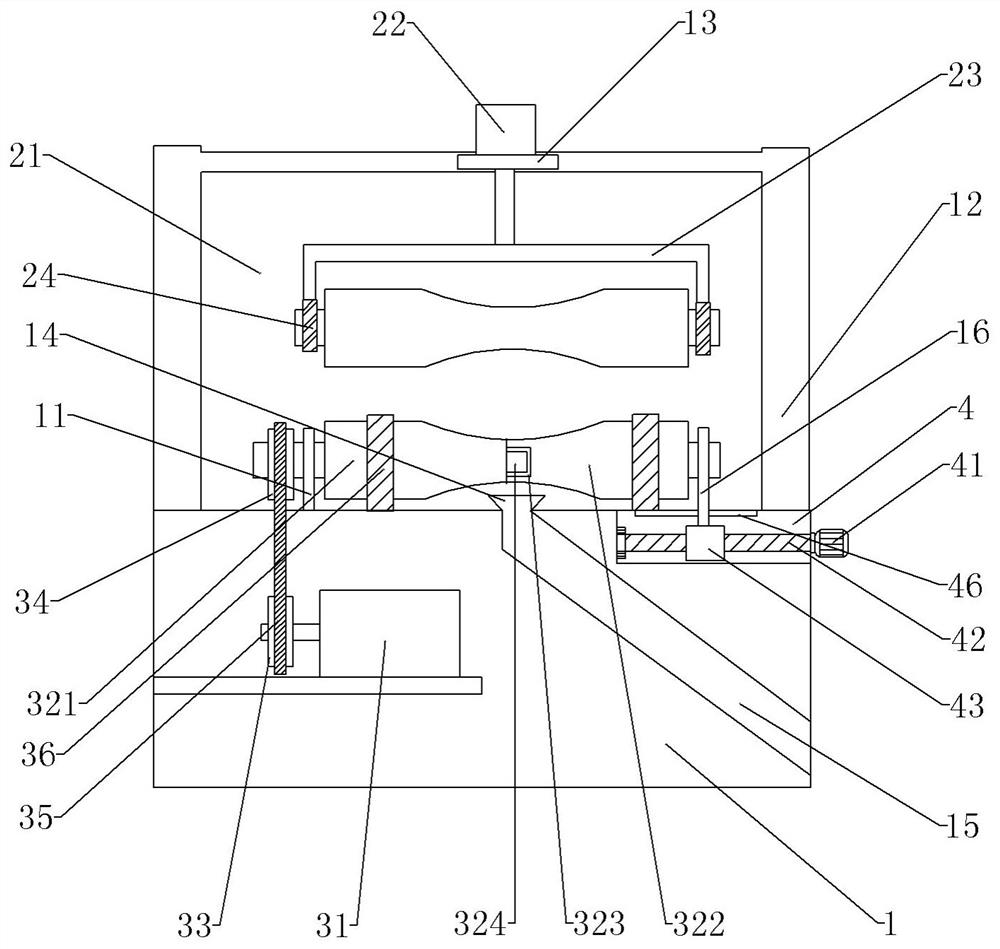
[0028] Such as Figure 1-3 As show...


PUM


Abstract

The invention relates to the technical field of steel bar processing equipment, in particular to a building steel bar cutting device, including a machine table, an upper limit mechanism and a lower material guide mechanism are respectively arranged on the upper and lower sides of the machine table, and a cutting device is arranged between the lower material guide mechanism and the lower material bin. Mechanism and placement mechanism, the placement mechanism includes a placement seat, and a limit mechanism is arranged in the lower material bin; when the rotating roller and the moving roller of the present invention are combined, the steel bar can be driven forward; Roll out from the discharge pipe to quickly complete the transportation and transfer of steel bars, reduce the process of artificial unloading, and improve the cutting efficiency; there is a storage slot on the inside of the placement seat, so that the debris generated during the cutting process falls into the storage slot. ; Avoid flying debris and pollute the environment; set a limit mechanism in the feeding bin to avoid manual measurement again and again, making cutting more convenient; the cut steel bars roll out along the material guide plate, which is convenient for quick collection of cut steel bars , to avoid artificial movement, but also reduce labor costs.

Description

technical field [0001] The invention relates to the technical field of steel bar processing equipment, in particular to a construction steel bar cutting device. Background technique [0002] Steel bar refers to the steel used for reinforced concrete and prestressed reinforced concrete, whose cross section is circular, sometimes square with rounded corners; including smooth round steel bar, ribbed steel bar, twisted steel bar; steel bar mainly bears tensile stress in concrete ; Deformed steel bars have greater bonding capacity with concrete due to the action of ribs, so they can better withstand external forces; steel bars are widely used in various building structures; especially large, heavy, light thin-walled and high-rise building structures At present, the truncation of building steel bars is usually carried out manually, which is not only inefficient, but also requires the cooperation of two or more people during the stage process. One person takes the steel bar, and th...

Claims


Application Information

Patent Timeline
Patent Type & Authority Patents(China)
IPC IPC(8): B21F11/00B21F23/00B08B15/04
CPCB21F11/00B21F23/00B08B15/04
Inventor 勾杰李东
Owner 河南航天建筑工程有限公司
Why Eureka
Try Eureka