
Oil cylinder pressing guide reinforcing structure

A technology for strengthening the structure and guiding mechanism, which is applied in the direction of metal processing equipment, metal processing machine parts, clamping, etc., and can solve the problems of increasing the horizontal area of ​​the clamping mechanism, low machining accuracy, and poor clamping rigidity, so as to improve production efficiency , The horizontal area is small, the effect of reducing tailings

Pending Publication Date: 2020-11-17
江苏宁兴恒力智能设备有限公司
View PDF0 Cites 0 Cited by
  • Summary
  • Abstract
  • Description
  • Claims
  • Application Information

AI Technical Summary

Problems solved by technology

The conventional fixture clamping method is a clamping cylinder plus a circular floating pressure block. The reason for using a circular pressure block is that the pressure blocks of other shapes will rotate during the clamping process and interfere with the tool. Adding a general-purpose guide rod guide mechanism to the clamping mechanism will greatly increase the horizontal area of ​​the clamping mechanism. At the same time, there is a large gap between the piston rod of the clamping cylinder and the floating pressure block. During the processing, the steel plate will be stressed and produce certain Displacement, poor clamping rigidity, low machining accuracy

Method used


Image

  • Oil cylinder pressing guide reinforcing structure
  • Oil cylinder pressing guide reinforcing structure
  • Oil cylinder pressing guide reinforcing structure

Examples


Embodiment Construction

[0016] Embodiments of the present invention are described in detail below, examples of which are shown in the drawings, wherein the same or similar reference numerals designate the same or similar elements or elements having the same or similar functions throughout. The embodiments described below by referring to the figures are exemplary and are intended to explain the present invention and should not be construed as limiting the present invention.

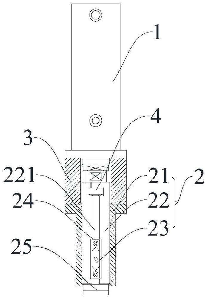
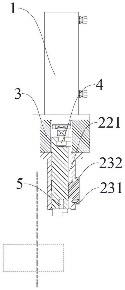
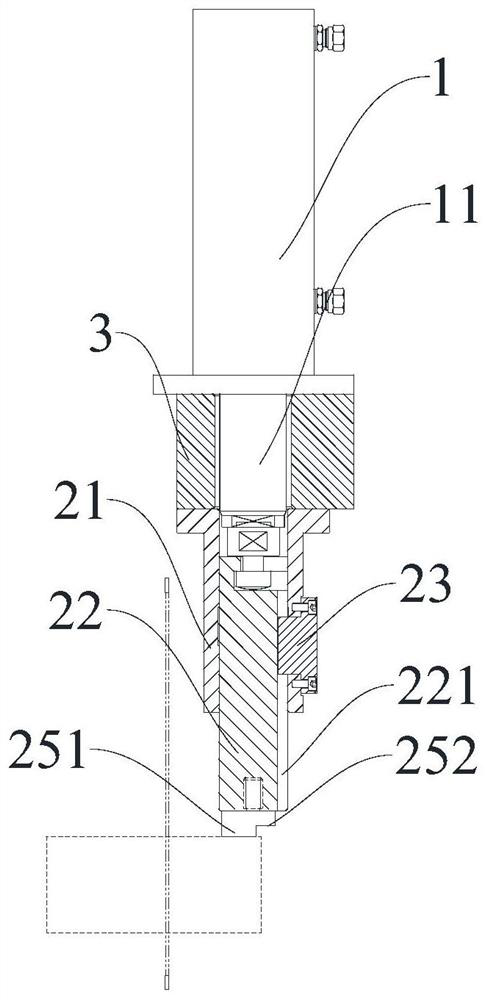
[0017] Such as Figure 1 to Figure 3 As shown, an oil cylinder compression guiding reinforcement structure includes a clamping oil cylinder 1, a guide mechanism 2 arranged on the clamping oil cylinder 1, the guide mechanism 2 includes a guide sleeve 21, a guide rod 22 and a guide key 23, and 21 sets of guide sleeves Connected to the piston rod 11 of the clamping cylinder 1, the bottom end of the guide sleeve 21 is connected with the clamping cylinder 1, the guide sleeve 21 is provided with a through hole 24, the guide rod 22 is i...


PUM


Abstract

The invention discloses an oil cylinder pressing guide reinforcing structure. The oil cylinder pressing guide reinforcing structure comprises a clamping oil cylinder and a guide mechanism arranged onthe clamping oil cylinder, wherein the guide mechanism comprises a guide sleeve, a guide bar and a guide key; the guide sleeve is connected to a piston rod of the clamping oil cylinder in a sleeved mode; the bottom end of the guide sleeve is connected to the clamping oil cylinder; a through hole is arranged in the guide sleeve; the guide bar is inserted into the guide sleeve and connected to the piston rod; a chute is arranged in the guide bar; a pressing block is arranged at the top end of the guide bar; the guide key is arranged in the through hole and fixedly connected to the guide sleeve;and one end of the guide key penetrates through the through hole, extends into the guide sleeve and abuts against the chute in order to drive the guide bar and the pressing block to do linear reciprocating motion in the guide sleeve through the piston rod under the limit of the guide key. The oil cylinder pressing guide reinforcing structure is easy to operate, small in horizontal area and capableof effectively increasing the clamping rigidity, improving the machining precision, shortening the clamping distance, reducing tailings and improving the production benefit.

Description

technical field [0001] The invention relates to the field of metal cutting and processing, in particular to an oil cylinder compression guiding reinforcement structure. Background technique [0002] In the field of metal cutting processing, hydraulic clamping is a universal and reliable clamping method. In the final stage of steel plate cutting into strips and blocks, because the size of the steel plate is too small, the clips cannot be clamped for processing. We call it tailings. Tailings are unavoidable in the production process, but try to minimize tailings. The size of the material is the key and difficult point for enterprises to reduce costs and increase benefits. The conventional fixture clamping method is a clamping cylinder plus a circular floating pressure block. The reason for using a circular pressure block is that the pressure blocks of other shapes will rotate during the clamping process and interfere with the tool. Adding a general-purpose guide rod guide me...

Claims


Application Information

Patent Timeline
IPC IPC(8): B23Q3/08
CPCB23Q3/082
Inventor 黄建勇孙德洲徐保群王勇
Owner 江苏宁兴恒力智能设备有限公司
Learn More