Rectifier production equipment
A technology for production equipment and rectifiers, which is used in metal processing equipment, grinding/polishing equipment, grinding machines, etc., to achieve the effect of convenient use, good effect, and easy clamping for production and processing
- Summary
- Abstract
- Description
- Claims
- Application Information
AI Technical Summary
Problems solved by technology
Method used
Image
Examples
Embodiment 1
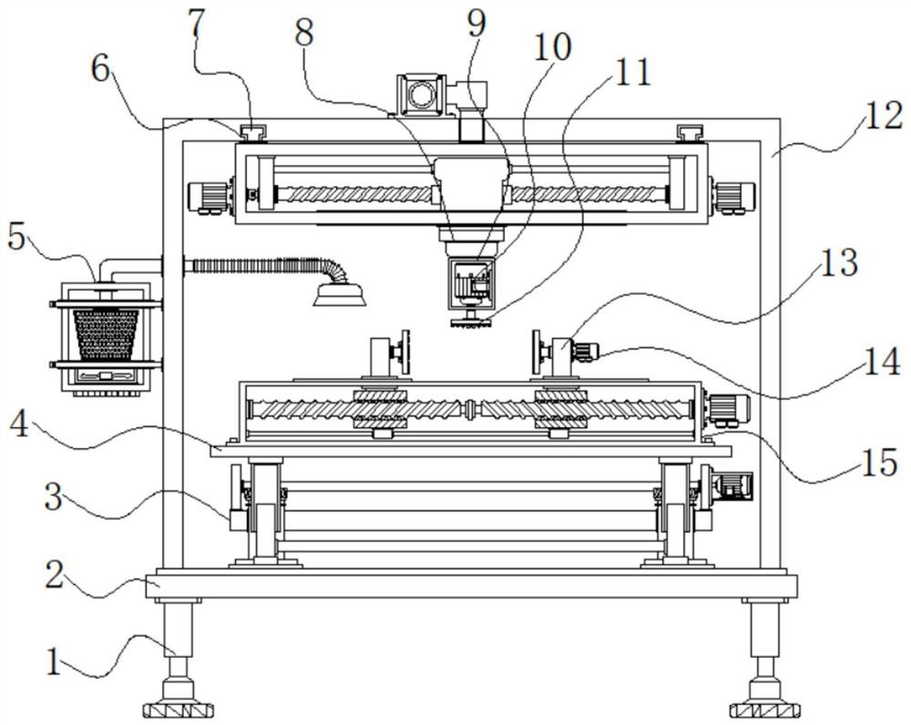
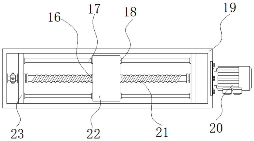
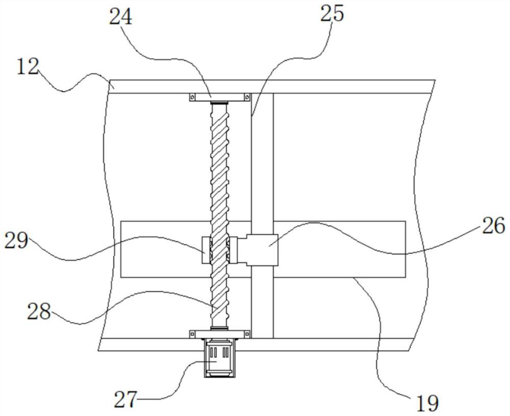
[0037] Example 1: See Figure 1-8 A rectifier production apparatus, comprising a base 2 and an outer frame 12, the bottom four corners of the base 2 are fixedly connected with the leg 1, the top of the base 2 is fixed to the outer frame 12 is connected to the top, the base 2 is provided with a lifting mechanism 3, the outer bottom of the inner frame 12 is provided with a table 4, a side of the outer frame 12 is provided with a dust removing means 5, the top of the inside of the outer frame 12 is provided with a cylinder 8, the cylinder 8 of the MPT may be a model, and a cylinder 8 a bottom end fixedly connected with a first drive motor 10, the first driving motor model 10 may be Y90L-2, inside the first drive motor 10 is fixedly connected with a first drive motor 10, and the output shaft of the first driving motor 10 9 through the bottom mount and fixedly connected with the grinding head 11, on both sides of the table top 4 are respectively provided with a clamp column 13, column 1...
Embodiment 2
[0041] Example 2: 3 by a bottom plate lifting mechanism 301, a bottom bar 302, horizontal plate 303, holder 304, upper frame 305, a shaft 306, a lumen 307, a first servo motor 308, a first bevel gear 309, a bottom cover 310, reinforcing bars 311, 312 and the movable column 303. the horizontal plate, a bottom plate 301 are fixedly connected to the top of the base 2 on both sides, both ends of the top plate 301 are fixedly connected to a bottom bar 302, are fixed between the bottom transverse rod 302 connected reinforcing rod 311, the top end of the rod 302 is inserted respectively have upper frame 305, the inner top frame 305 is provided with a lumen 307, respectively, to the top of the top frame 305 are fixedly connected to the bottom sides of the table 4, the top plate 301 are respectively fixedly connected at an intermediate position of the bottomed sleeve 310, the top of the bottom cover 310 is movably connected with a first bevel gear 309, a first helical gear between the top ...
Embodiment 3
[0044] Example 3: 5 by the dust removal mechanism holder 501, a housing 502, vacuum blower 503, a dust bag 504, the conduit 505, the corrugated tube connecting the vacuum port 506 and 507 composed of a connecting bracket 501 are fixed to the outer frame 12 side, is connected between the holder 501 is fixed housing 502, and a bottom end inside the housing 502 is fixedly connected with a suction fan 503, the suction fan 503 may be a model BFX-100, top housing 502 is provided inside the dust collecting Bag 504, top housing 502 is fixedly connected with a conduit 505, and the side of the catheter 505 through the side of the outer frame 12 and fixedly connected with the corrugated pipe 506 is connected, and the bottom end of the corrugated pipe 506 is connected with a suction port 507 is fixedly connected ;
[0045] Internal conduit 505 side of the corrugated pipe 506 is connected in communication, the other side of the conduit 505 to the top of the housing 502 through the dust bag 504...
PUM
 Abstract
Description
Claims
Application Information
 - R&D
- Intellectual Property
- Life Sciences
- Materials
- Tech Scout
- Unparalleled Data Quality
- Higher Quality Content
- 60% Fewer Hallucinations
Browse by: Latest US Patents, China's latest patents, Technical Efficacy Thesaurus, Application Domain, Technology Topic, Popular Technical Reports.
© 2025 PatSnap. All rights reserved.Legal|Privacy policy|Modern Slavery Act Transparency Statement|Sitemap|About US| Contact US: help@patsnap.com


