Precision casting sand blasting device

A sandblasting device and technology for precision castings, applied in the direction of explosion generating devices, used abrasive processing devices, spray guns, etc., can solve the inconvenience of precision castings for sandblasting, inconsistent sandblasting and polishing, and stable manual holding Poor performance and other problems, to achieve the effect of facilitating comprehensive sandblasting, improving sandblasting efficiency, and increasing practicability

Inactive Publication Date: 2021-11-16
ANHUI SOLID FOUNDRY CO LTD
View PDF0 Cites 1 Cited by
  • Summary
  • Abstract
  • Description
  • Claims
  • Application Information

AI Technical Summary

Problems solved by technology

[0003] In the existing sandblasting process, the castings are generally held manually through gloves, and then the surface of the castings is sandblasted and polished by manually using a spray gun. However, due to the poor stability of manual holding, it is very easy to The degree of sandblasting and polishing at each position is not uniform, resulting in poor overall polishing effect of the castings, and some sandblasting devices are used for sandblasting, but the existing sandblasting devices are not convenient for the removal of precision castings before and after sandblasting. put

Method used


Image

  • Precision casting sand blasting device
  • Precision casting sand blasting device
  • Precision casting sand blasting device

Examples


Embodiment 1

[0032] A sandblasting device for precision castings, comprising a sandblasting box 3, the lower end of the sandblasting box 3 is provided with a support leg 1, and a workbench 8 is arranged inside the sandblasting box 3, and both sides of the lower end of the workbench 8 are provided with lifting mechanisms 2;

[0033] Lifting mechanism 2 comprises the first electric motor 205 that is fixed on the inner bottom of sandblasting box 3, and the output end of first electric motor 205 is provided with second gear 204, and the outside of second gear 204 is provided with the first gear 203 of meshing connection, the first The middle of the gear 203 is provided with a first threaded rod 201, and the upper end of the first threaded rod 201 runs through the workbench 8 to be provided with a fixed block 202, and the first threaded rod 201 is threadedly connected with the workbench 8; the lower end of the workbench 8 is provided with a limit rod 9. A sleeve 10 is arranged on the outside of...

Embodiment 2

[0036] As an option, see figure 1 , Figure 5-6 , a sandblasting device for precision castings, a clamping mechanism 7 is arranged above the workbench 8;

[0037]The clamping mechanism 7 includes two groups of moving seats 707 arranged on the top of the workbench 8. The inner sides of the two groups of moving seats 707 are provided with clamping plates 703. Pad 23; the lower ends of the two groups of moving seats 707 are provided with a fixed plate 702, the lower end of the fixed plate 702 is provided with a moving block 701, the moving block 701 is arranged on the inside of the workbench 8, and the inner thread of the moving block 701 is connected with a second threaded rod 704, the second threaded rod 704 is provided with two groups, and the direction is oppositely arranged, and one end of the second threaded rod 704 is all rotatably connected on the inner wall of the workbench 8, and the other end of the second threaded rod 704 is provided with the first bevel gear 705 Th...

Embodiment 3

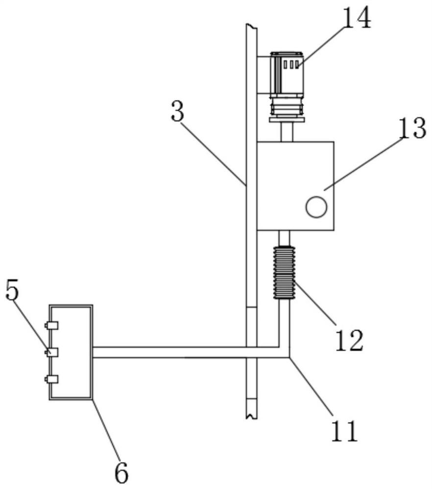
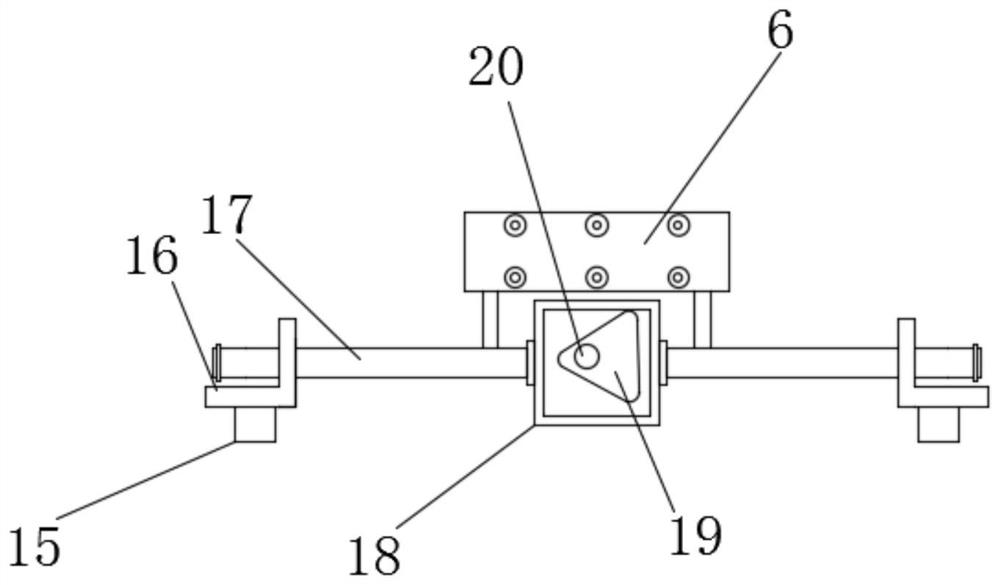
[0041] As an option, see Figure 1-4 , a sandblasting device for precision castings, a sandblasting box 6 is arranged on the top of the workbench 8, a plurality of groups of nozzles 5 are arranged on the surface of the sandblasting box 6, and one end of a connecting pipe 11 is arranged on the rear side of the sandblasting box 6, and the connecting pipe 11 The other end is connected with elastic bellows 12, and one end of elastic bellows 12 is connected with sand material box 13, and sand material box 13 is fixed on the outside of sandblasting box 3, and one side of sand material box 13 is provided with air pump 14, sandblasting box The lower end of 6 is provided with fixed rod 4, and the lower end of fixed rod 4 is provided with sliding rod 17, and the middle of sliding rod 17 is provided with frame plate 18, and the inside of frame plate 18 is provided with turning block 19, in order to drive sandblasting box 6 reciprocating Movement, the turning block 19 is set as a triangul...


PUM


Abstract

The invention discloses a precision casting sand blasting device, and belongs to the technical field of sand blasting devices. The precision casting sand blasting device comprises a sand blasting box, supporting legs are arranged at the lower end of the sand blasting box, a workbench is arranged in the sand blasting box, lifting mechanisms are arranged on the two sides of the lower end of the workbench, each lifting mechanism comprises a first motor fixed to the bottom end of the interior of the sand blasting box, and a second gear is arranged at the output end of each first motor. The height position of the workbench is adjusted for lowering, a precision casting can be conveniently taken and placed, the first motors are controlled to rotate, the second gears are driven to rotate, the second gears drive first gears to rotate, first threaded rods are driven to rotate, the workbench ascends and descends, through limiting rods and sleeves, the workbench is limited in the vertical direction, stable ascending and descending of the workbench are ensured, the precision casting can be conveniently placed and taken out before and after sand blasting machining, the sand blasting efficiency is improved, and the precision casting sand blasting device is simple in structure and convenient to use.

Description

technical field [0001] The invention belongs to the technical field of sandblasting devices, in particular to a sandblasting device for precision castings. Background technique [0002] Sand blasting is the process of cleaning and roughening the surface of the substrate by the impact of high-speed sand flow. Compressed air is used as the power to form a high-speed jet beam to spray the spray material to the surface of the workpiece to be processed at high speed, so that the appearance or shape of the outer surface of the workpiece surface changes, which is often used in the polishing of castings. [0003] In the existing sandblasting process, the castings are generally held manually through gloves, and then the surface of the castings is sandblasted and polished by manually using a spray gun. However, due to the poor stability of manual holding, it is very easy to The degree of sandblasting and polishing at each position is not uniform, resulting in poor overall polishing e...

Claims


Application Information

Patent Timeline
Patent Type & Authority Applications(China)
IPC IPC(8): B24C3/18B24C5/04B24C9/00
CPCB24C3/18B24C5/04B24C9/00B24C9/003
Inventor 刘锐汪李劼刘彬彬常勤祥
Owner ANHUI SOLID FOUNDRY CO LTD
Why Eureka
Try Eureka