
Working method of robot system

A technology of a robot system and a working method, applied in the working field of the robot system, can solve the problems of silk relaxation, insufficient space to set up a hollow channel, and inability to achieve jetting, etc.

Active Publication Date: 2020-11-17
CHANGSHA UNIVERSITY OF SCIENCE AND TECHNOLOGY
View PDF7 Cites 3 Cited by
  • Summary
  • Abstract
  • Description
  • Claims
  • Application Information

AI Technical Summary

Problems solved by technology

[0005]1. Due to the complex structure of the wire-driven snake-arm robot in the prior art, there is not enough space to set up a hollow channel to realize fluid transportation
[0006]2. In the existing wire-driven snake-arm robot, the joint rotation center is usually at the symmetrical position of the joint, which will make the wire-driven snake-arm robot bend , or when the driving position remains unchanged, and there is an external lateral force, the wire usually relaxes
[0007]3. In the long-distance injection structure of the prior art, either the injection direction is single, or the driving structure is complex, and there is not enough space and support near the injection head for complicated installation nozzle direction adjustment device
[0008]4. The spraying structure of the prior art can only realize spraying with one degree of freedom, such as spraying in the direction of parallel spraying heads, or spraying in rotation, but not two jetting in the direction of freedom
[0009]5. The combination of the rotating disks in the prior art can only realize the relative movement of the two, but cannot realize the combined movement of the two
[0010]6. In the prior art, for the injection structure that cooperates with the robot arm, due to the limited space, it is difficult to set up an additional drive structure to achieve more complex functions

Method used


Image

  • Working method of robot system
  • Working method of robot system
  • Working method of robot system

Examples


Embodiment Construction

[0042] Invention point of the present invention is as follows:

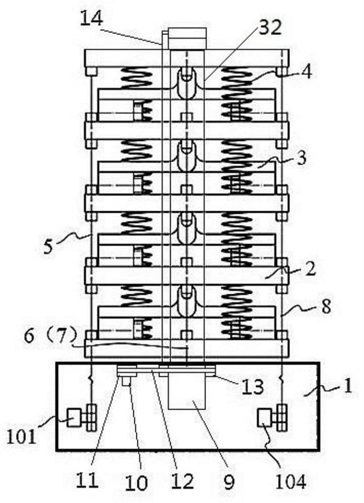
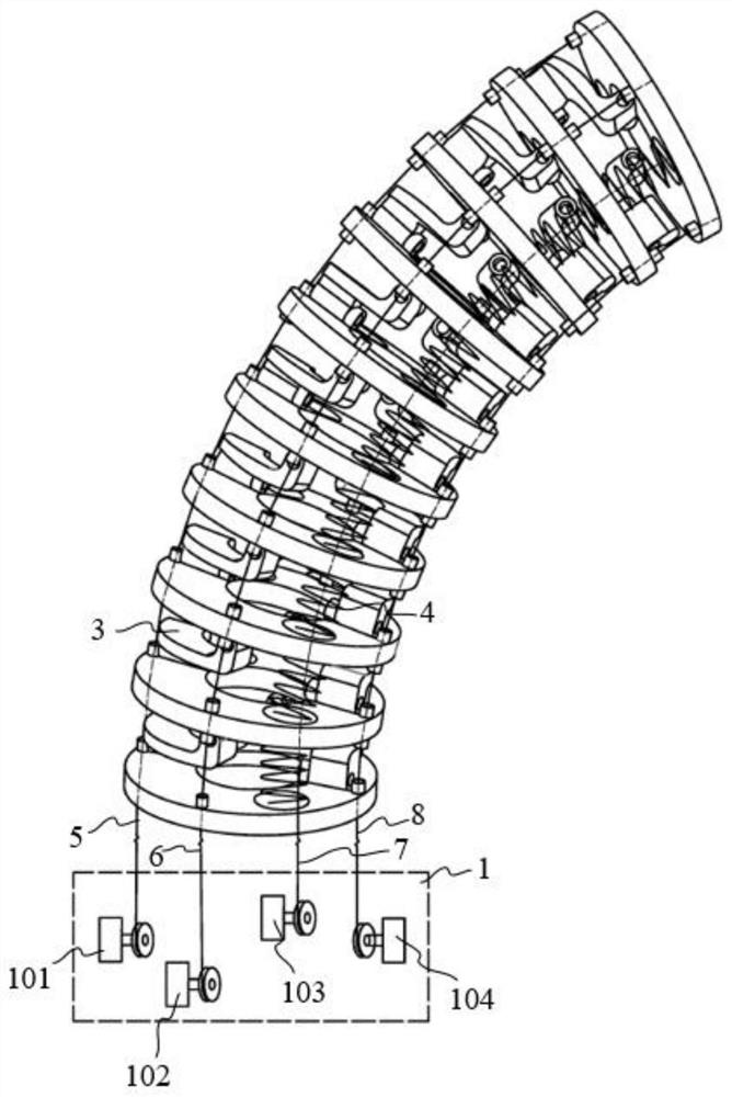
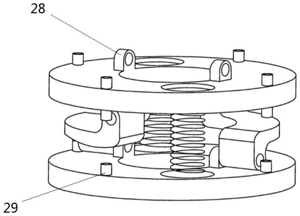
[0043] 1. Regarding the first point of the background technology, through the shape of the two space connecting rods 3, a hollow channel is reserved to realize fluid transportation.

[0044]2. With regard to the second point of the background technology, through the positions of the lugs 30 of the two space connecting rods 3 , the position and angle transformation between the spacer plates 2 can be more flexibly realized, and more flexible deformation can be realized.

[0045] 3. Regarding the third point of the background technology, the pendulum 15 is driven by the inner drawing wire 14 to rotate, so as to realize multi-directional spraying.

[0046] 4. For the fourth point of the background technology, through the relative movement between the two turntables, the two working modes of parallel spraying head spraying in direction or spraying in rotation can be switched.

[0047] 5. Regarding the fifth point of ...


PUM


Abstract

The invention discloses a working method of a robot system. The robot system comprises a workbench, bottom wheels, a machine body, a driving module, a control module, a hydraulic module, a communication module and a snakelike arm module, wherein the workbench is arranged above the machine body, six bottom wheels are arranged below the machine body, directions of the six bottom wheels are adjustable, and the driving module drives the bottom wheels to move through a transmission mechanism. The working method comprises a working in-place method, a jetting and spraying method and an adjusting feedback method.

Description

technical field [0001] The invention relates to the field of robots, in particular to a working method of a robot system. Background technique [0002] Snake arm robot is widely used in maintenance inspection, medical treatment and other fields because it can realize multi-degree-of-freedom bending motion and can move flexibly in a restricted environment. The driving methods of snake-arm robots mainly include wire drive, pneumatic muscle drive and shape memory alloy drive. Because the wire drive method can make the snake-arm robot occupy a small space and have significant advantages such as low motion inertia, it is widely used in snake-arm robots. designing. [0003] In recent years, researchers at home and abroad have successively proposed many wire-driven snake-arm robots with different configurations, which generally consist of a driving device and several identical rotating joints. According to the number of degrees of freedom, existing rotary joints are divided into ...

Claims


Application Information

Patent Timeline
Patent Type & Authority Applications(China)
IPC IPC(8): B25J9/06B25J9/16
CPCB25J9/065B25J9/1615
Inventor 黄龙刘北尹来容王金行胡波
Owner CHANGSHA UNIVERSITY OF SCIENCE AND TECHNOLOGY
Learn More