Batting puffing device for spinning

A puffing device and technology of using cotton tires, which are applied in the field of cotton textile processing, can solve the problem of cotton wool sticking to the tooth pressure under the grinding and pressing plate, and achieve the effect of ensuring the working environment

Inactive Publication Date: 2020-11-17
山东瑞达纺织有限公司
View PDF6 Cites 8 Cited by
  • Summary
  • Abstract
  • Description
  • Claims
  • Application Information

AI Technical Summary

Problems solved by technology

[0004] Based on the technical problem that the existing grinding and pressing device tends to stick cotton wool to the tooth pressure under the grinding and pressing plate after a period of grinding and pressing, the present invention proposes a cotton batting puffing device for textile use

Method used


Image

  • Batting puffing device for spinning
  • Batting puffing device for spinning
  • Batting puffing device for spinning

Examples


Embodiment 1

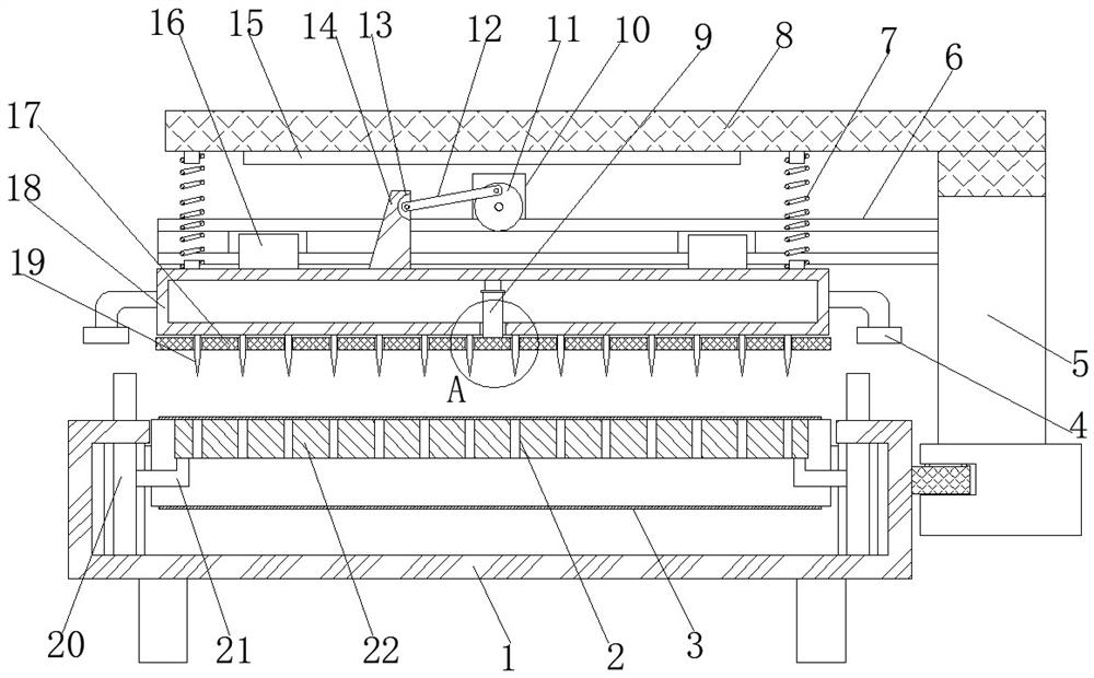
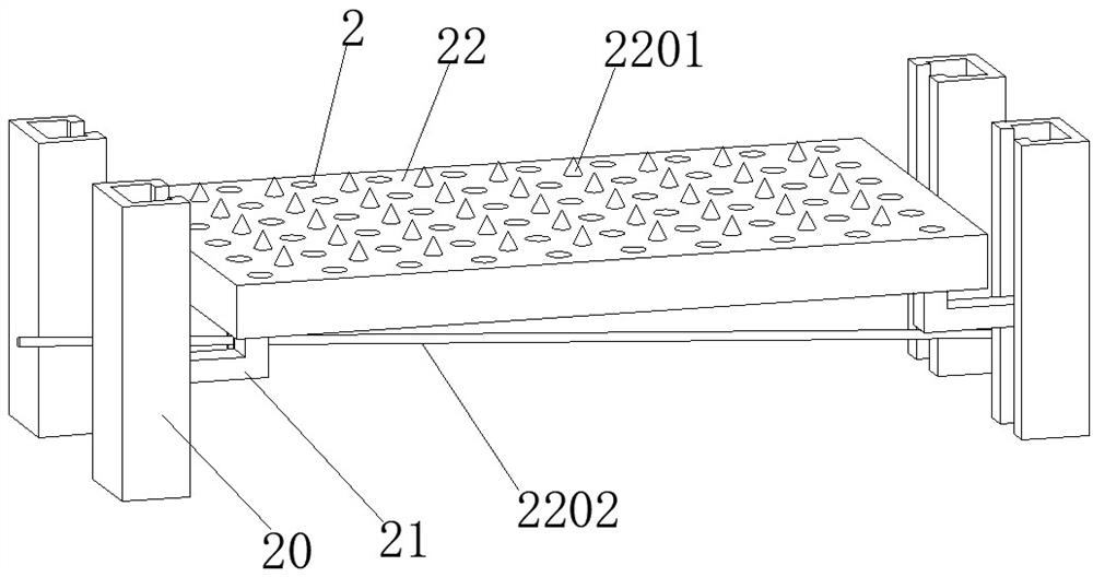
[0028] refer to Figure 1-5 , a cotton batt puffing device for textiles, comprising a base 1 with an upward cross-section having a C-shaped structure, the groove bottom of the base 1 is rotatably connected to both ends of the drive roller 301, and the outer walls of the two drive rollers 301 The same conveying mesh belt 3 is wound between them, and the lower surface near the top conveying mesh belt 3 is provided with a lifting pallet 22, the side of the base 1 is fixed with a slide rail, and a sliding support frame 5 is slidably connected to the slide rail, and the sliding support The two sides of the frame 5 near the top are respectively fixed with C-shaped steel beams 6 with opposite openings. The same pressure plate 18 is slidably connected between the two C-shaped steel beams 6. The pressure plate 18 is a hollow structure, and there is a round hole in the middle of the bottom of the pressure plate 18. , the top inner wall of the pressure plate 18 is fixed with an electric ...

Embodiment 2

[0038] refer to figure 1 and image 3, a cotton batt bulking device for weaving, compared with Embodiment 1, this embodiment also includes.

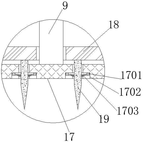
[0039] In the present invention, the lower surface of the clamping plate 17 is provided with stepped through holes 1702 equidistantly distributed and adapted to the diameter of the vertebral body 19, and the stepped through holes 1702 are all sleeved with cleaning rings 1701, and the inner walls of the cleaning rings 1701 are provided with Has 1703 bristles.

[0040] When the present invention is in use: the fluff stuck on the vertebral body 19 can be cleaned by controlling the elongation of the electric push rod 9 extension rod.


PUM


Abstract

The invention belongs to the technical field of cotton textile processing, particularly relates to a batting puffing device for spinning, aims to solve the problem that according to an existing grinding and pressing device, after grinding and pressing are conducted for a period of time, cotton fibers are prone to adhering to tooth pressure below a grinding and pressing plate, and provides the following scheme. The batting puffing device for spinning comprises a base with an upward opening and having a cross section of a C-shaped structure, driving rollers are rotatably connected to the positions, close to the two ends, of the groove bottom of the base, one same conveying mesh belt is wound between the outer walls of roller bodies of the two driving rollers, a lifting supporting plate is arranged at the position, close to the top end, of the lower surface the conveying mesh belt, a sliding rail is fixed to the side face of the base, and a sliding supporting frame is slidably connected to the sliding rail; and C-shaped steel cross beams with opposite openings are fixed to the positions, close to the top end, of the two sides of the sliding supporting frame correspondingly, one same pressing plate is slidably connected between the two C-shaped steel cross beams, and the pressing plate is of a hollow structure. According to the batting puffing device for spinning, the problem thataccording to the existing grinding and pressing device, after grinding and pressing are conducted for a period of time, the cotton fibers are prone to adhering to the tooth pressure below the grindingand pressing plate is solved.

Description

technical field [0001] The invention relates to the technical field of cotton textile processing, in particular to a cotton batt expanding device for textile. Background technique [0002] At present, the grinding and pressing process of quilt processing relies entirely on manual grinding and pressing with smooth circular grinding and pressing wooden boards. The entire grinding and pressing process is time-consuming and laborious. Generally, it is very difficult for a worker to process three quilts a day, and the production efficiency Low; and when manual grinding is used, the grinding pressure and degree are uneven in the whole grinding process, which directly affects the processing quality and service life of the quilt. , It directly affects that the whole cotton quilt cannot keep warm and use normally. [0003] After retrieval, the Chinese patent is a quilt processing grinding device disclosed in CN201811073154.8, which includes a horizontally arranged cotton batting pla...

Claims


Application Information

Patent Timeline
Patent Type & Authority Applications(China)
IPC IPC(8): D04H1/02B08B1/00
CPCD04H1/02B08B1/008
Inventor 李积红吴坚华
Owner 山东瑞达纺织有限公司
Why Eureka
Try Eureka