
Method for predicting fatigue life of adhesive joint in full-service temperature interval

A technology for fatigue life prediction and service temperature, which is applied in the field of fatigue performance testing of bonded joints, and can solve problems such as failure to achieve fatigue life prediction, pressure on bonded joints, and low efficiency.

Active Publication Date: 2020-11-17
JILIN UNIV
View PDF9 Cites 0 Cited by
  • Summary
  • Abstract
  • Description
  • Claims
  • Application Information

AI Technical Summary

Problems solved by technology

[0003] When studying the force of the adhesive in the actual structure, since the force analysis of the entire bonded structure cannot be carried out in the actual experiment, the force of the adhesive in the actual structure can only be simulated through the bonded joint
The main shortcomings and deficiencies of the current bonded joint fatigue test device are: the existing fatigue loading device can only apply loads in the shear direction and tensile direction to the bonded joint, and cannot make the bonded joint bear pressure, so the existing fatigue The device can only apply a cyclic load with r>0; the existing fatigue device is sensitive to non-axial load, and the specimen is easy to bear the non-axial load; when the existing fatigue device performs fatigue work on the specimen, the specimen stretches It is easy to shake and has a great impact on the life of the loading device; the existing fatigue loading device and test method are mainly aimed at normal temperature conditions, and the influence of temperature is not fully considered; the existing fatigue loading device can usually only load a single specimen; the existing The fatigue loading device can only load a single specimen, and the efficiency is low; the existing fatigue performance test method cannot realize the fatigue life prediction under any stress range within a certain temperature range under any cycle characteristics

Method used


Image

  • Method for predicting fatigue life of adhesive joint in full-service temperature interval
  • Method for predicting fatigue life of adhesive joint in full-service temperature interval
  • Method for predicting fatigue life of adhesive joint in full-service temperature interval

Examples


Embodiment

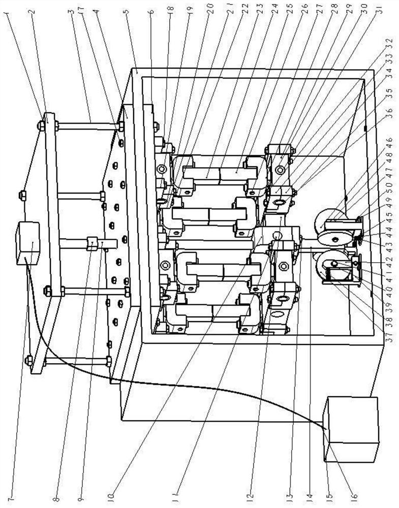
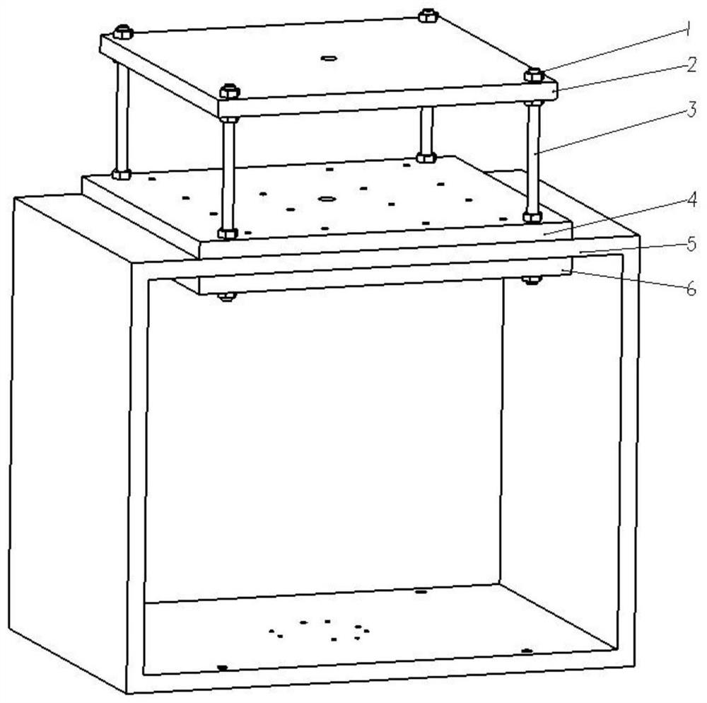
[0103] Such as figure 1 As shown, the method for predicting fatigue life of bonded joints under the full service temperature range provided in the present invention is tested by using a multi-specimen bonded joint tension-compression fatigue test device based on the consideration of temperature effects. The multi-specimen bonded joint tension The main structure of the pressure fatigue test device is composed of an environmental chamber device, a power input device, an upper compression device, an adhesive joint, a specimen support cross shaft device, a lower compression device, a movable limiter device, and a fixed limiter device. .

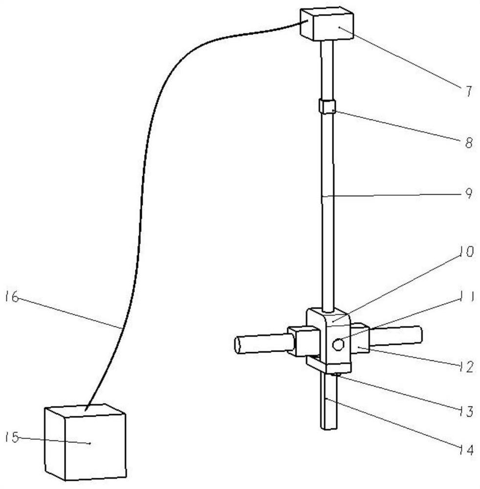
[0104] Among them, the environment box device mainly includes: oil cylinder support plate 2, threaded rod 3, environment box upper support plate 4, environment box 5, environment box lower support plate 6; power input device mainly includes: oil cylinder 7, sensor 8, telescopic rod 9 , U-shaped part 10, balance beam pin shaft 11, first-level bal...


PUM

PropertyMeasurementUnit
diameteraaaaaaaaaa

Abstract

The invention discloses a method for predicting the fatigue life of an adhesive joint in a full-service temperature interval, and the method comprises the following steps: 1, building a function thatthe failure strength changes along with the temperature after the quasi-static failure strength of the adhesive joint at different temperatures is measured in the full-service temperature interval ofa vehicle body; 2, determining the fatigue loading frequency of the bonding joint; 3, carrying out fatigue tests on the bonding joint at different temperatures, and establishing S-N curve functions atdifferent temperatures after obtaining the maximum stress in the cyclic stresses with the specified service life at different temperatures; 4, fitting fatigue parameters in the S-N curve functions atdifferent temperatures into a function related to the test temperature, further obtaining a stress amplitude-temperature-fatigue fracture cycle life fitting function, and fitting the stress amplitudetemperature fatigue fracture cycle life fitting function into a T-S-N fatigue performance curved surface; and step 5, obtaining dangerous point stress during quasi-static stretching of the joint according to the temperature influence factor, judging a corresponding external load cycle characteristic value in the actual joint fatigue life to be predicted, and finally obtaining the actual cycle life of the bonded joint according to the T-S-N fatigue performance curved surface.

Description

technical field [0001] The invention relates to the technical field of fatigue performance testing of bonded joints, in particular to a method for predicting the fatigue life of bonded joints under a full service temperature range. Background technique [0002] Vehicles are subjected to dynamic alternating loads from many aspects during driving, which makes the body bonding structure prone to fatigue damage during long-term service, which seriously affects vehicle safety. At the same time, during the actual operation of the vehicle, the bonding structure of the vehicle body is often affected by factors such as temperature, humidity, salt spray, and ultraviolet rays. Different environmental factors have a greater impact on the performance of the bonding joint. Considering that sealants and coatings can be used to effectively reduce the influence of humidity, salt spray and ultraviolet rays, temperature has become the most important factor affecting the performance of bonded s...

Claims


Application Information

Patent Timeline
Patent Type & Authority Applications(China)
IPC IPC(8): G01N19/04
CPCG01N19/04
Inventor 李锋徐千卉那景新慕文龙谭伟王广彬冯耀娄菲陈宏利孟欢
Owner JILIN UNIV
Learn More