Hydrogen diluting equipment applied to fuel cell system

A fuel cell system, hydrogen technology, applied in fuel cells, electrical components, circuits, etc., can solve problems such as potential safety hazards, reduced hydrogen concentration, poor dilution effect, etc., to achieve the effect of improving safety

Inactive Publication Date: 2020-11-17
ZHONGSHAN FRED MACHINERY CO LTD
View PDF0 Cites 0 Cited by
  • Summary
  • Abstract
  • Description
  • Claims
  • Application Information

AI Technical Summary

Problems solved by technology

At present, the volume of the container used to dilute hydrogen is fixed. When the amount of hydrogen discharged from the dilution container does not meet the emission standards, it is difficult to further reduce the concentration of hydrogen in the dilution container, the dilution effect is not good, and there are potential safety hazards

Method used


Image

  • Hydrogen diluting equipment applied to fuel cell system
  • Hydrogen diluting equipment applied to fuel cell system
  • Hydrogen diluting equipment applied to fuel cell system

Examples


Embodiment Construction

[0022] In order to make the technical means, creative features, goals and effects achieved by the present invention easy to understand, the present invention will be further described below in conjunction with specific embodiments.

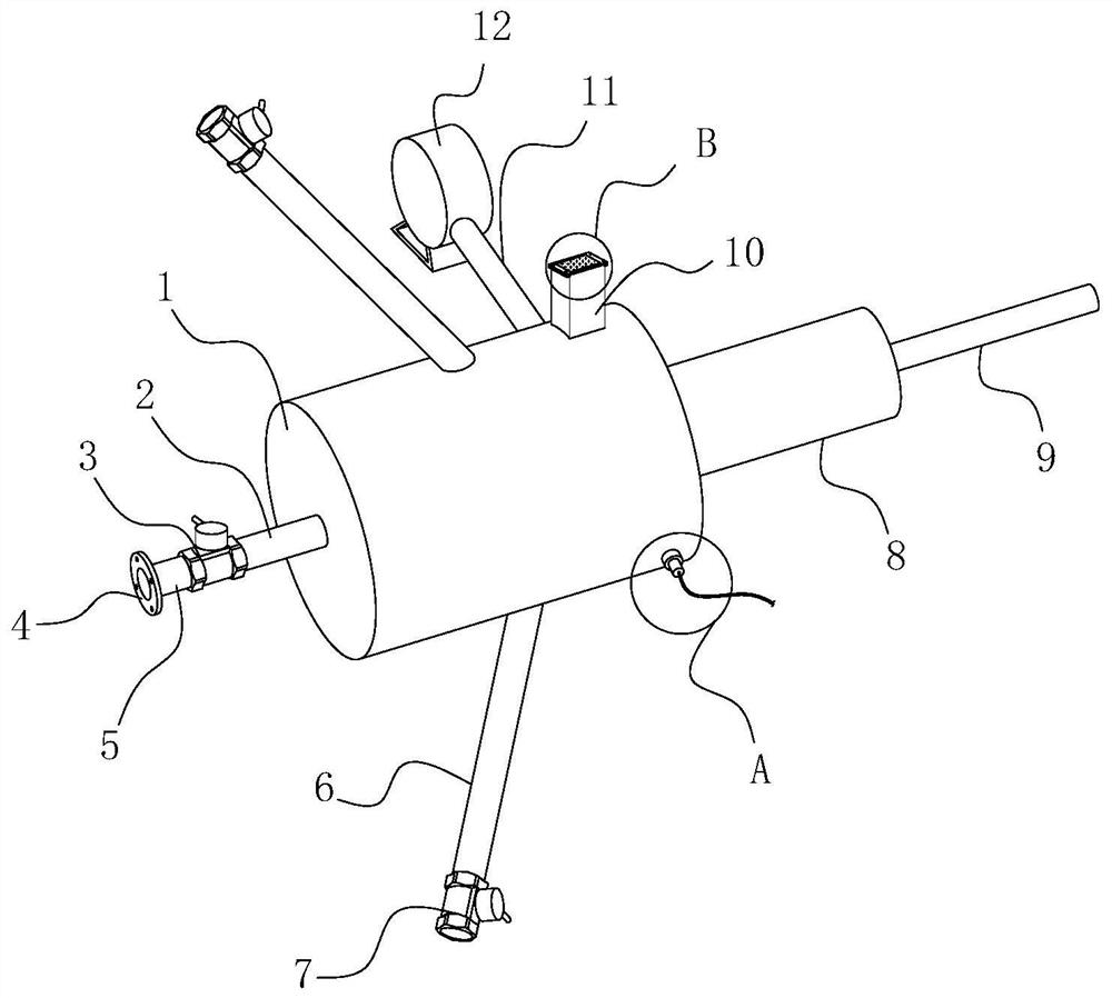
[0023] see Figure 1 to Figure 6 , the present invention provides a technical solution: a hydrogen dilution device applied to a fuel cell system, including a dilution cylinder 1, a pipe joint 2 is fixedly connected to the middle of one side of the dilution cylinder 1, and the pipe joint 2 is far away from the dilution cylinder 1 One end is connected with the first electromagnetic valve 3 connected with the output end of the PLC controller, and the pipe joint 2 plays the role of connecting the first electromagnetic valve 3 and the dilution cylinder 1 .

[0024] The end of the first electromagnetic valve 3 away from the pipe joint 2 is connected to the connecting pipe 5 for connecting the exhaust port of the fuel cell, and the outer surface of the c...


PUM


Abstract

The invention provides hydrogen diluting equipment applied to a fuel cell system, which comprises a diluting cylinder, a pipe joint is fixedly connected to the middle position of one surface of the diluting cylinder, and one end, far away from the diluting cylinder, of the pipe joint is connected with a first electromagnetic valve connected with the output end of a PLC (Programmable Logic Controller); a branch pipe is installed on the outer surface of the end, away from the pipe connector, of the dilution barrel, the end, away from the dilution barrel, of the branch pipe is connected with a first one-way valve communicated in the direction of the dilution barrel, a through opening is formed in the middle of the face, away from the pipe connector, of the dilution barrel, and a cylinder fixedly connected with the dilution barrel is arranged on the outer side of the through opening; compared with the prior art, the hydrogen diluting device has the advantages that the volume of the dilutedhydrogen container can be adjusted, and the volume of the diluted hydrogen container can be adjusted by the aid of the hydrogen diluting device.

Description

technical field [0001] The invention relates to a hydrogen dilution device applied to a fuel cell system, belonging to the technical field of fuel cells. Background technique [0002] A fuel cell is a power generation device that converts the chemical energy of fuel directly into electrical energy. In actual use, in order to discharge the water vapor and nitrogen gas that diffuse back from the cathode side to the anode, the anode side needs to discharge exhaust gas regularly according to the hydrogen concentration. Exhaust gas is diluted. At present, the volume of the container used to dilute hydrogen is fixed. When the amount of hydrogen discharged from the dilution container does not meet the emission standards, it is difficult to further reduce the concentration of hydrogen in the dilution container, the dilution effect is not good, and there are potential safety hazards. Contents of the invention [0003] In view of the deficiencies in the prior art, the purpose of t...

Claims


Application Information

Patent Timeline
Patent Type & Authority Applications(China)
IPC IPC(8): H01M8/0444H01M8/04746B01D46/10
CPCB01D46/10H01M8/04462H01M8/04761Y02E60/50
Inventor 崔新刚谷国涛张小岗
Owner ZHONGSHAN FRED MACHINERY CO LTD
Why Eureka
Try Eureka