
Cable erecting and supporting device for electromechanical installation

A support device and installation technology, which is applied in the direction of cable suspension device, overhead line/cable equipment, etc., can solve the problems of sawtooth and fixed pin easily slipped by force, cable damage, support rod toppling, etc., to reduce manual adjustment. time, increase stability, avoid the effect of incorrect adjustment angle

Inactive Publication Date: 2020-11-17
吴振亮
View PDF7 Cites 5 Cited by
  • Summary
  • Abstract
  • Description
  • Claims
  • Application Information

AI Technical Summary

Problems solved by technology

The rotating plate in the above-mentioned patent has the following disadvantages: the top of the rotating plate is fixed with a vertical plate, and the vertical plate will drive the rotating plate to move when fixing the cables. Because some cables are heavy, the saw teeth on the side of the rotating plate and the fixing pins are easy to slip under force. Causes the mast to fall and the cable to fall to the ground causing damage

Method used


Image

  • Cable erecting and supporting device for electromechanical installation
  • Cable erecting and supporting device for electromechanical installation
  • Cable erecting and supporting device for electromechanical installation

Examples


Embodiment Construction

[0029] The technical solution of the present patent will be described in further detail below in conjunction with specific embodiments.

[0030] Embodiments of the present patent are described in detail below, examples of which are illustrated in the accompanying drawings, wherein the same or similar reference numerals refer to the same or similar elements or elements having the same or similar functions throughout. The embodiments described below with reference to the accompanying drawings are exemplary and are only used to explain the present patent, but should not be construed as a limitation on the present patent.

[0031] In the description of this patent, it should be understood that the terms "center", "upper", "lower", "front", "rear", "left", "right", "vertical", "horizontal", The orientation or positional relationship indicated by "top", "bottom", "inner", "outer", etc. is based on the orientation or positional relationship shown in the drawings, and is only for the ...


PUM


Abstract

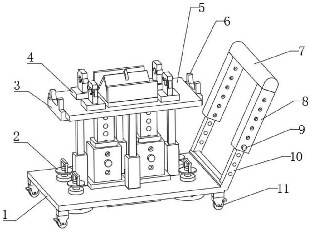
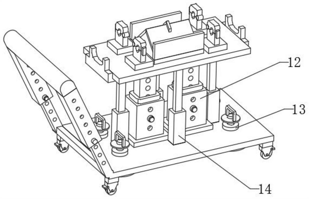
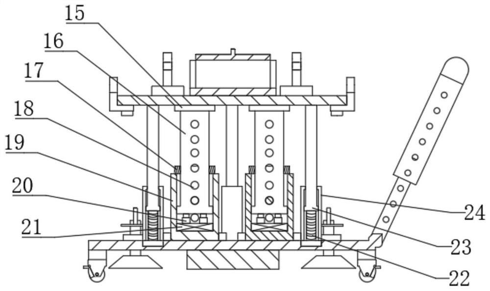
The invention discloses a cable erecting and supporting device for electromechanical installation, relates to the technical field of cable erecting, and aims at to solve the problem that a cable is prone to sliding to the ground to be damaged. The device specifically comprises a bottom plate and a movable plate; a lifting mechanism is fixedly installed on the outer wall of the top of the bottom plate, a guide mechanism is fixedly installed on the outer wall of the top of the bottom plate, a sucker mechanism is fixedly installed on the inner wall of one side of the bottom plate, and a first wire groove and a second wire groove are fixedly formed in the outer walls of the two sides of the movable plate; a fixed plate is fixedly installed on the outer wall of the top of the movable plate; a lower fixed block is fixedly installed on the outer wall of the top of the fixed plate, an upper movable block is movably connected to the outer wall of one side of the lower fixed block through a rotating shaft, and second fixed buckles are fixedly installed on the outer walls of one sides of the lower fixed block and the upper movable block; a base plate is fixedly installed on the outer wall ofthe top of the movable plate; a side plate is fixedly installed on the outer wall of the top of the base plate; a first movable cover plate and a second movable cover plate are movably installed on the outer walls of the side plate. The device is good in stability, and a fixed cable cannot slip off from the movable plate.

Description

technical field [0001] The invention relates to the technical field of cable erection, in particular to a cable erection support device for electromechanical installation. Background technique [0002] A cable is a conductor made of one or more mutually insulated conductors and an outer insulating protective layer, which transmits power or information from one place to another. During the cable installation process of electromechanical equipment, the electromechanical equipment needs Conducting power test, the cable is easily damaged when placed directly on the ground, so a device for lifting and fixing the cable is required. [0003] After searching, the Chinese patent application number CN210074681U discloses a cable erection support device for electromechanical installation, including a mounting block, a chute, a ground angle, a fixed rod, a connecting head and a connecting sliding rod; The top end is connected with the connecting block on the lower end face of the insta...

Claims


Application Information

Patent Timeline
Patent Type & Authority Applications(China)
IPC IPC(8): H02G1/04H02G7/05
CPCH02G1/04H02G7/05
Inventor 吴振亮刘东吴艳
Owner 吴振亮
Learn More