A fast-laying railway engineering cable

A railway engineering and fast technology, applied in the direction of cable joints, circuits, electrical components, etc., can solve problems such as troublesome operation, and achieve the effect of easy docking, good traction effect, and preventing the sliding of the movable ring

Active Publication Date: 2021-11-19
ANHUI HUATONG CABLE GRP
View PDF8 Cites 0 Cited by
  • Summary
  • Abstract
  • Description
  • Claims
  • Application Information

AI Technical Summary

Problems solved by technology

[0004] The purpose of the present invention is to solve the shortcomings in the prior art that there is troublesome operation when laying and connecting, improving work strength and reducing work efficiency, and proposes a railway engineering cable that can be quickly laid

Method used


Image

  • A fast-laying railway engineering cable
  • A fast-laying railway engineering cable
  • A fast-laying railway engineering cable

Examples


Embodiment 1

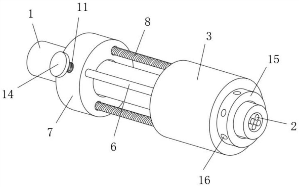
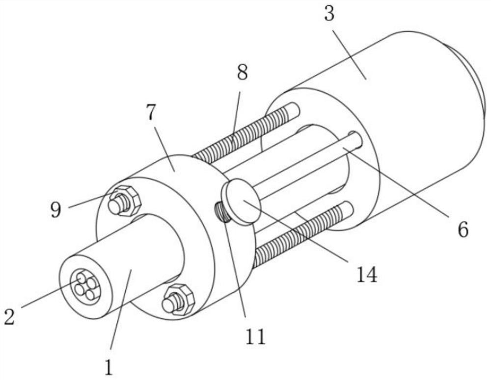
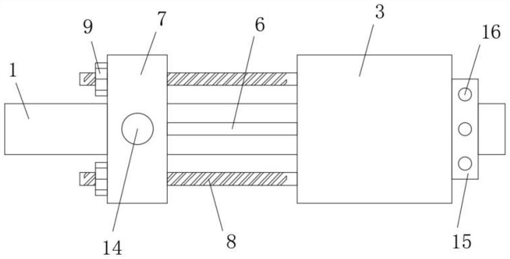
[0030] refer to Figure 1-8 , a railway engineering cable that can be quickly laid, including a cable body 1, a cable core 2 is provided inside the cable body 1, a butt joint protection collar 3 is provided on the outer wall side of the cable body 1 sliding sleeve, and the butt joint protection collar 3 The inner wall is provided with a chute 4, the inner wall of the chute 4 is sealed and slidably connected with a slip ring 5, and the slip ring 5 is connected with the outer wall of the cable body 1 by a sealing and sliding sleeve, and one side of the slip ring 5 is symmetrically fixedly connected with two connecting rods 6. Both ends of the two connecting rods 6 extend to the outside of the docking protective collar 3 and are fixedly connected with the same movable ring 7, and the movable ring 7 is sleeved and connected with one side of the outer wall of the cable body 1, and the movable rings 7 are connected to each other. Two clamping assemblies are arranged symmetrically on...

Embodiment 2

[0032]Further improvement on the basis of Embodiment 1: the side of the butt joint protective collar 3 away from the convex ring 15 is symmetrically fixedly connected with two limit screw rods 8, and one side of the two limit screw rods 8 respectively passes through the movable ring 7 away from the One side of the docking protective collar 3 extends to the outside of the movable ring 7, and one side of the two limit screw rods 8 is threaded with a limit nut 9, and one side of the two limit nuts 9 is connected to the movable ring 7 respectively. The side away from the docking protective collar 3 is in contact, and through the cooperation of the limit screw 8 and the limit nut 9, the butt joint protective collar 3 and the movable ring 7 can be limited. The arc-shaped groove 10, the inner wall of the arc-shaped groove 10 away from the cable body 1 is threaded through the clamping screw 11, and the end of the clamping screw 11 close to the cable body 1 is rotatably connected with a...


PUM


Abstract

The invention belongs to the technical field of cable laying, in particular to a railway engineering cable that can be quickly laid. Aiming at the problems of troublesome operation, increased work intensity and reduced work efficiency in the existing laying connection, the following scheme is proposed, which includes the cable body, the The inside of the cable body is provided with a cable core, and the outer wall of the cable body is provided with a butt joint protective collar, and the inner wall of the butt joint protective collar is provided with a chute, and the inner wall of the chute is sealed and slidably connected with a slip ring. In the invention, the sliding of the movable ring can drive the overall sliding of the docking protective collar, which facilitates the docking of cable bodies of different lengths, and the cable body can be clamped by turning the knob, while preventing the sliding of the movable ring. Through the cooperation of the connecting track and the convex ring, the two butt protection collars can be limitedly connected, which is easy to operate, convenient to use, reduces the working intensity, and thus greatly improves the working efficiency.

Description

technical field [0001] The invention relates to the technical field of cable laying, in particular to a railway engineering cable that can be quickly laid. Background technique [0002] The railway signal photoelectric integrated cable is based on the original railway axle counting cable, and uses optical fiber and shielded communication group to transmit optical and electrical information. It has the characteristics of strong anti-electromagnetic interference, transmits railway axle counting signals, and ensures train driving safety. This product can transmit data information, audio signal, transmit electric energy and carry out long-distance or interval communication in the railway signal system. In the construction of the national railway network, railway engineering signal cables are widely used, and there are also a large number of applications in the construction of rail transit. They are indispensable cable products for the construction of high-speed railways and rail...

Claims


Application Information

Patent Timeline
Patent Type & Authority Patents(China)
IPC IPC(8): H02G15/18H02G3/06H01R24/38H01R13/639H01R13/629
CPCH01R13/629H01R13/639H01R24/38H02G3/06H02G15/18
Inventor 陶天宝陈浩李小康陈国林李业胜王敏鲁男子
Owner ANHUI HUATONG CABLE GRP
Why Eureka
Try Eureka