Control instrument with wire guide structure

A technology of guiding structure and control instrument, applied in chemical instruments and methods, cleaning methods using tools, cleaning methods and utensils, etc. problem, to achieve the effect of fixing convenient and fast

Pending Publication Date: 2020-11-17
PUTIAN UNIV
View PDF0 Cites 1 Cited by
  • Summary
  • Abstract
  • Description
  • Claims
  • Application Information

AI Technical Summary

Problems solved by technology

[0004] The purpose of the present invention is: in order to solve the problem that some control instruments today are not equipped with any wire guide structure, the wires on the instrument are generally in a single direction, and when installing and wiring the instrument, it is impossible to follow the wiring position according to the wiring position. Quickly change the position of the wire, and at the same time, it is impossible to quickly fix the changed wire position. The use effect is not good, and some control instruments today are not equipped with automatic dust removal and heat dissipation structures, resulting in poor heat dissipation for the control instrument. The effect of cleaning dust is not good, and a control instrument with a wire-guided structure is proposed

Method used


Image

  • Control instrument with wire guide structure
  • Control instrument with wire guide structure
  • Control instrument with wire guide structure

Examples


Embodiment Construction

[0039] The following will clearly and completely describe the technical solutions in the embodiments of the present invention with reference to the accompanying drawings in the embodiments of the present invention. Obviously, the described embodiments are only some, not all, embodiments of the present invention. Based on the embodiments of the present invention, all other embodiments obtained by persons of ordinary skill in the art without creative efforts fall within the protection scope of the present invention.

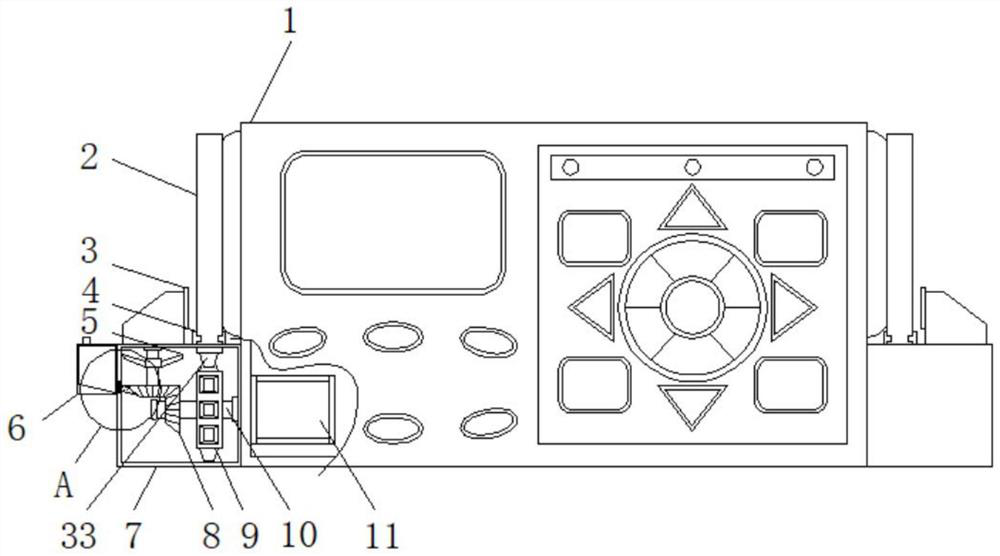
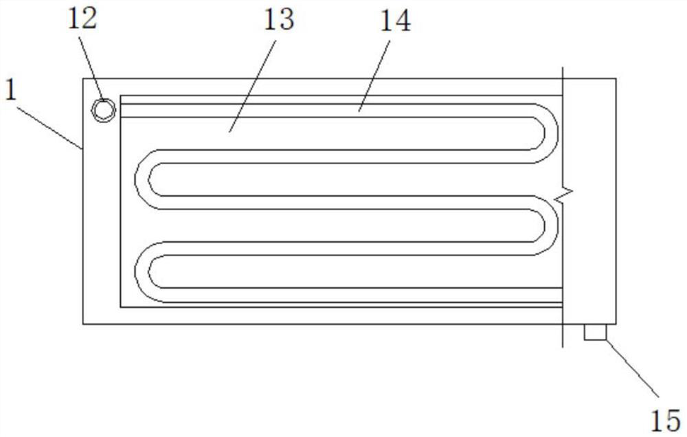
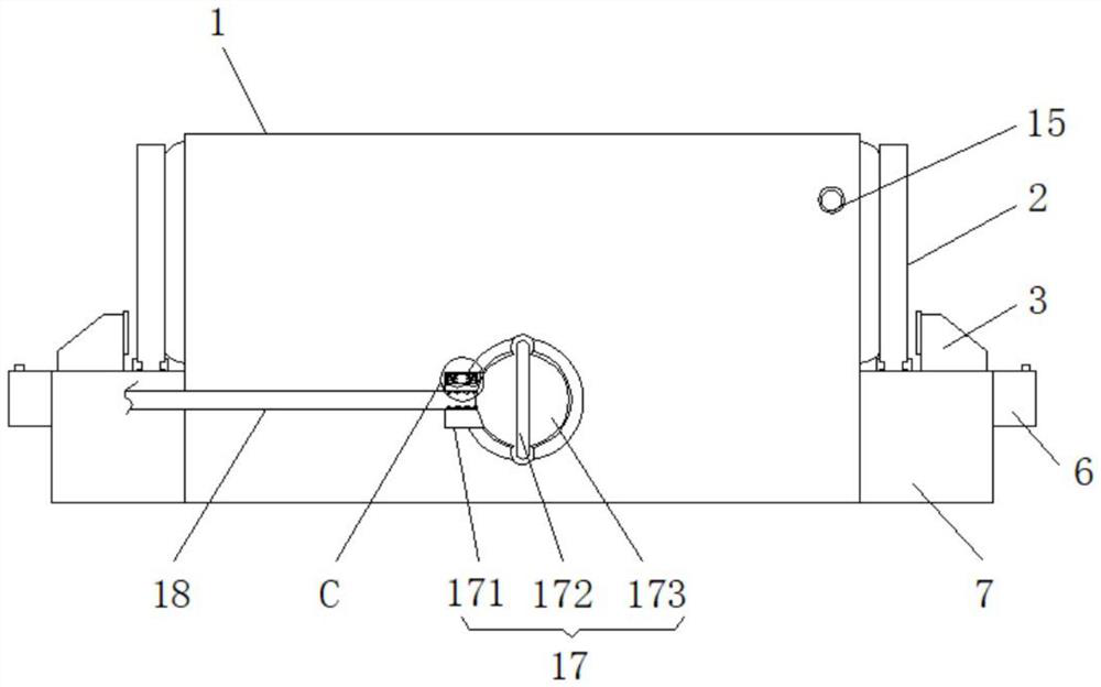
[0040] see Figure 1-7, the present invention provides a technical solution: a control instrument with a wire-guiding structure, including a casing 1, a side casing 7, a drive motor 11, an inclined heat sink 13, a wire-guiding mechanism 17, and a T-shaped shaft 29. Side shells 7 are fixedly installed on the outer walls of both sides of the casing 1, an oil box 6 is fixedly installed on one side outer wall of the side casing 7, and a driving motor 11 is fixedly inst...


PUM


Abstract

The invention discloses a control instrument with a wire guide structure, which belongs to the field of control instruments, and comprises a casing, side shells, a driving motor, an inclined heat dissipation plate, a wire guide mechanism and a T-shaped shaft, the side shells are fixedly mounted on the outer walls of the two sides of the casing, and an oil box is fixedly mounted on the outer wall of one side of each side shell. A driving motor is fixedly installed on the inner wall of the machine shell. The rotatable wire guide mechanism is installed in a matched mode, when an instrument needsto be installed and wired, the position and the angle direction of a wire are changed by rotating the wire guide mechanism according to the position where wiring is needed, then wiring is conducted, the direction of the wire can be rapidly changed, wiring is convenient, and when the angle is rotated, a handle is pulled up to make the positioning shaft and the positioning groove disengage and rotate the mounting disc. When the wire guide mechanism needs to be fixed, the handle is directly loosened, the connecting spring enables the positioning shaft to be clamped into the positioning groove, then the wire guide mechanism can be fixed, and fixing is convenient and fast.

Description

technical field [0001] The invention belongs to the technical field of control instruments, in particular to a control instrument with a wire guiding structure. Background technique [0002] With the development and progress of science and technology, in some mechanical production fields, in order to improve production efficiency and production quality, and reduce human labor, some mechanical automation equipment is generally introduced. These mechanical automation equipment can work automatically and process parts. , to improve the processing efficiency of parts, and the control of these mechanical automation requires the use of control instruments, through which people can set programs or mediate processes for mechanical equipment. [0003] Nowadays, some control instruments are not equipped with any wire guide structure. The wires on the instrument are generally in a single direction. When installing and wiring the instrument, it is impossible to quickly change the positi...

Claims


Application Information

Patent Timeline
Patent Type & Authority Applications(China)
IPC IPC(8): H05K5/02B08B1/00B08B1/02B08B5/02H05K7/20F16H57/04
CPCB08B1/00B08B1/001B08B1/02B08B5/02F16H57/045F16H57/0467H05K5/0213H05K5/0217H05K5/0247H05K7/20136H05K7/20218H05K7/20418
Inventor 宋丽涵唐元林林丽芳
Owner PUTIAN UNIV
Why Eureka
Try Eureka