
Waste cable recycling device

A waste cable recycling technology, applied in recycling technology, electronic waste recycling, lighting and heating equipment, etc., can solve the problems of reducing the working efficiency of the device, reducing the cleaning effect of the device, and difficult cleaning by the operator, so as to improve the work Efficiency, reduced wear, improved maneuverability

Inactive Publication Date: 2020-11-20
衡阳市华南电线有限公司
View PDF11 Cites 1 Cited by
  • Summary
  • Abstract
  • Description
  • Claims
  • Application Information

AI Technical Summary

Problems solved by technology

[0002] Cables are usually rope-like cables twisted by several wires or groups of wires. As the use of cables is becoming more and more extensive, there are more and more waste cables produced by various demolition, and these cables are not damaged. , but it looks bent and old, and it can still be recycled; the waste cable recycling equipment in the prior art, because the cable is exposed to wind and rain for a long time, some dirt is easy to stick to the surface, making it difficult for operators to clean it. thereby reducing the working efficiency of the device
[0003] For example, Chinese patent announcement number CN108580383A discloses a waste cable recycling equipment, which is basically described as: open the first motor to drive the turntable to rotate through the rotating shaft, and use the connecting rod to make the movable block reciprocate on the guide rod to drive the installation. The barrel cleans the surface of the old cable back and forth, connects the annular water spray pipe to the water pipe, and washes the old cable to wash off the stains; in fact, when in use, the surface of the cleaned cable is prone to water stains , leading to more obvious water stain marks after drying, thus reducing the cleaning effect of the device

Method used


Image

  • Waste cable recycling device
  • Waste cable recycling device
  • Waste cable recycling device

Examples


Embodiment Construction

[0026] The following will clearly and completely describe the technical solutions in the embodiments of the present invention with reference to the accompanying drawings in the embodiments of the present invention. Obviously, the described embodiments are only some, not all, embodiments of the present invention. Based on the embodiments of the present invention, all other embodiments obtained by persons of ordinary skill in the art without making creative efforts belong to the protection scope of the present invention.

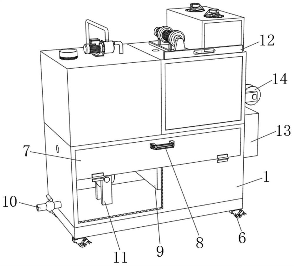
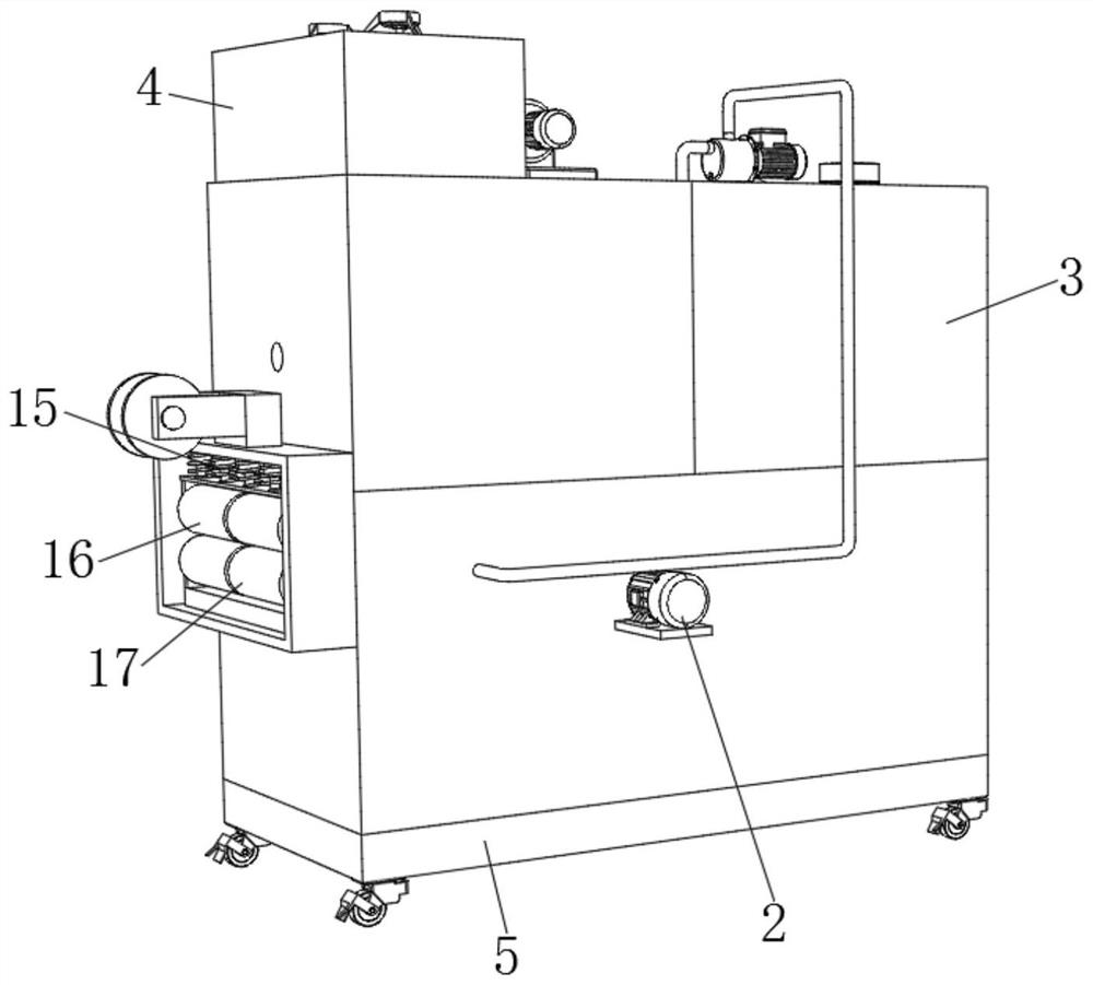
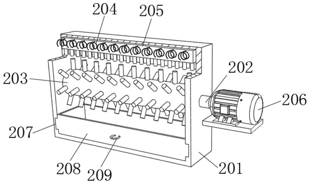
[0027] see Figure 1-5 , the present invention provides a technical solution: a waste cable recovery and reuse equipment, including a treatment box 1, a cleaning device 2 is fixedly connected to the right side of the rear side wall of the treatment box 1, and a cleaning device 2 is fixedly connected to the left side of the upper surface of the treatment box 1. There is a cleaning device 3, the right side of the upper surface of the processing box 1 is fixedly ...


PUM


Abstract

The invention relates to the technical field of cable recovery, and discloses a waste cable recycling device. The waste cable recycling device comprises a treatment box, wherein a clearing device is fixedly connected to the right side of the rear side wall in the treatment box, a washing device is fixedly connected to the left side of the upper surface of the treatment box, and a drying device isfixedly connected to the right side of the upper surface of the treatment box. According to the waste cable recycling device, a cable is brought into a water zone through a first guide wheel for soaking, and then the clearing device and the washing device cooperate with each other, so that the time required by operators to manipulate the device to remove dirt on the surface of the cable is shortened, the phenomenon that it is difficult for the operators to clear adhesive dirt caused by wind and rain of the cable for a long time is reduced, the working efficiency of the device is improved, water stains on the outer surface of the cable are cleared and wiped off through an upper-layer roller and a lower-layer roller, the device can wipe off the water stain marks on the surface of the cable,and the clearing effect of the device is enhanced.

Description

technical field [0001] The invention relates to the technical field of cable recovery, in particular to equipment for recycling waste and old cables. Background technique [0002] Cables are usually rope-like cables twisted by several wires or groups of wires. As the use of cables is becoming more and more extensive, there are more and more waste cables produced by various demolition, and these cables are not damaged. , but it looks bent and old, and it can still be recycled; the waste cable recycling equipment in the prior art, because the cable is exposed to wind and rain for a long time, some dirt is easy to stick to the surface, making it difficult for operators to clean it. Thereby reducing the work efficiency of this device. [0003] For example, Chinese patent announcement number CN108580383A discloses a waste cable recycling equipment, which is basically described as: open the first motor to drive the turntable to rotate through the rotating shaft, and use the conne...

Claims


Application Information

Patent Timeline
Patent Type & Authority Applications(China)
IPC IPC(8): B08B3/04B08B3/02B08B1/02B08B3/14B08B13/00H01B15/00F26B13/00F26B13/28F26B13/10F26B21/00B08B1/20
CPCB08B3/041B08B3/022B08B3/14B08B13/00H01B15/00F26B13/00F26B13/28F26B13/10F26B21/001F26B21/004B08B1/20Y02W30/82
Inventor 尹宣尹树清尹万仓伍建元罗红英
Owner 衡阳市华南电线有限公司
Learn More