Probe clamping equipment for scanning probe machining

A technology of scanning probes and clamping equipment, applied in the field of probes

Inactive Publication Date: 2020-11-20
沈祥青
View PDF0 Cites 3 Cited by
  • Summary
  • Abstract
  • Description
  • Claims
  • Application Information

AI Technical Summary

Problems solved by technology

[0003] However, the existing clamping equipment also needs to clean the surface of the probe with the electro-corrosion solution after the probe is made, then dry the probe, and then perform the next step of processing. Therefore, those skilled in the art provide A probe clamping device for scanning probe processing is developed to solve the problems raised in the above-mentioned background technology

Method used


Image

  • Probe clamping equipment for scanning probe machining
  • Probe clamping equipment for scanning probe machining
  • Probe clamping equipment for scanning probe machining

Examples


Embodiment Construction

[0021] The following will clearly and completely describe the technical solutions in the embodiments of the present invention with reference to the accompanying drawings in the embodiments of the present invention. Obviously, the described embodiments are only some, not all, embodiments of the present invention. Based on the embodiments of the present invention, all other embodiments obtained by persons of ordinary skill in the art without making creative efforts belong to the protection scope of the present invention.

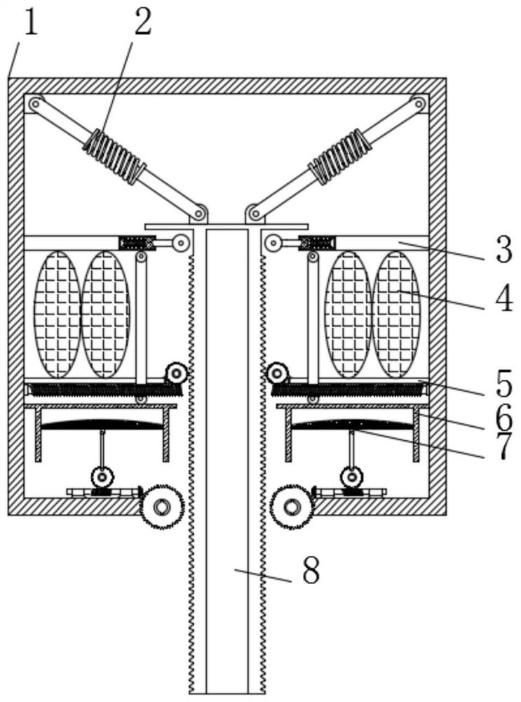
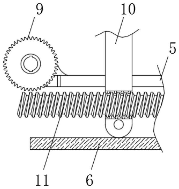
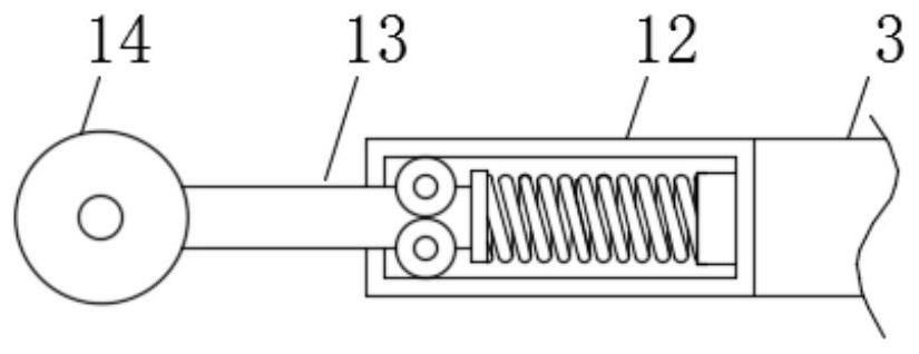
[0022] see Figure 1-5 , a probe clamping device for scanning probe processing, including a housing 1, the bottom of the lower surface of the housing 1 is rotatably connected with a first worm gear 15, the number of the first worm gear 15 is two, and the first worm gear 15 is The left-right symmetrical arrangement is located on both sides of the clamping block 8 , the first worm wheel 15 is engaged with the clamping block 8 , and the clamping block 8 is slidab...


PUM


Abstract

The invention relates to the technical field of probes, in particular to probe clamping equipment for scanning probe machining. The probe clamping equipment comprises a shell. The bottom end of the lower surface of the shell is rotationally connected with first worm wheels. The positions, located in the middles of the first worm wheels, of the lower surface of the shell are in sliding connection with a clamping block. The upper surface of the clamping block is rotationally connected with spring supporting rods. The clamping block is driven by a probe to slide downwards in the shell, then the first worm wheels engaged with the clamping block are driven to rotate synchronously in the process that the clamping block slides downwards, and then second worm wheels above worms are driven to do circular motion; pistons are pulled through connecting rods to slide up and down in gas cylinders; when the pistons slide up and down in the gas cylinders, gas in the gas cylinders is subjected to suction motion, then a gas pipe is connected with a water box to push out water in the water box, the surface of the probe is cleaned, and electrolytes on the surface of the probe are thoroughly cleaned away; and electrolytes are prevented from influencing the next machining of the probe, and the production efficiency of the probe is improved.

Description

technical field [0001] The invention relates to the technical field of probes, in particular to a probe clamping device for scanning probe processing. Background technique [0002] The scanning probe is the part used for scanning during the use of the instrument. In the production process of the probe, the method of immersion in the electro-corrosion solution is used to manufacture the probe. The probe precursor is statically corroded in the electro-corrosion solution, and real-time Monitor the electrolytic current during corrosion, and prepare the scanning probe by the method of scanning the tip of the scanning probe, which is convenient, fast, and low in cost. The characteristic size and the geometric surface shape of the probe tip are controllable. During the production process, clamping equipment is required for production. . [0003] However, the existing clamping equipment also needs to clean the surface of the probe with the electro-corrosion solution after the probe...

Claims


Application Information

Patent Timeline
Patent Type & Authority Applications(China)
IPC IPC(8): B08B3/04F26B21/00B08B13/00
CPCB08B3/04B08B13/00F26B21/004
Inventor 沈祥青
Owner 沈祥青
Why Eureka
Try Eureka