Forging device for iron pan manufacturing

A forging and iron pot technology, applied in forging/pressing/hammer devices, manufacturing tools, cleaning methods and utensils, etc., can solve problems such as time-consuming, potential safety hazards, sore arms of craftsmen, etc. forging effect

Inactive Publication Date: 2020-11-20
钟和平
View PDF8 Cites 4 Cited by
  • Summary
  • Abstract
  • Description
  • Claims
  • Application Information

AI Technical Summary

Problems solved by technology

[0005] In order to overcome the shortcomings of hundreds of times of manual forging in the production of wrought iron pans, which is time-consuming, and long-term forging is likely to cause sore arms of craftsmen and has potential safety hazards, the purpose of the present invention is to provide an easy-to-operate, automatic iron pan. Forging device for turning iron pot

Method used


Image

  • Forging device for iron pan manufacturing
  • Forging device for iron pan manufacturing
  • Forging device for iron pan manufacturing

Examples


Embodiment 1

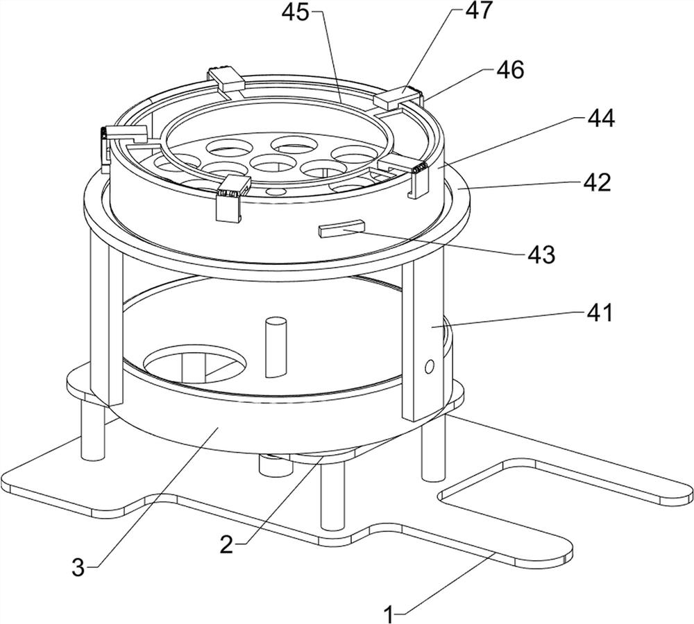
[0024] Such as Figure 1-4 As shown, a forging device for making iron pans includes a base 1, a placing platform 2, a waste hopper 3, a clamping device 4 and a hammering device 5, and the top of the base 1 is provided with a placing platform 2 connected by bolts. A waste hopper 3 is arranged on the top of the placing platform 2 , a clamping device 4 is arranged on the top of the base 1 , the clamping device 4 is located directly above the waste hopper 3 , and a hammering device 5 is arranged on the right side of the top of the base 1 .

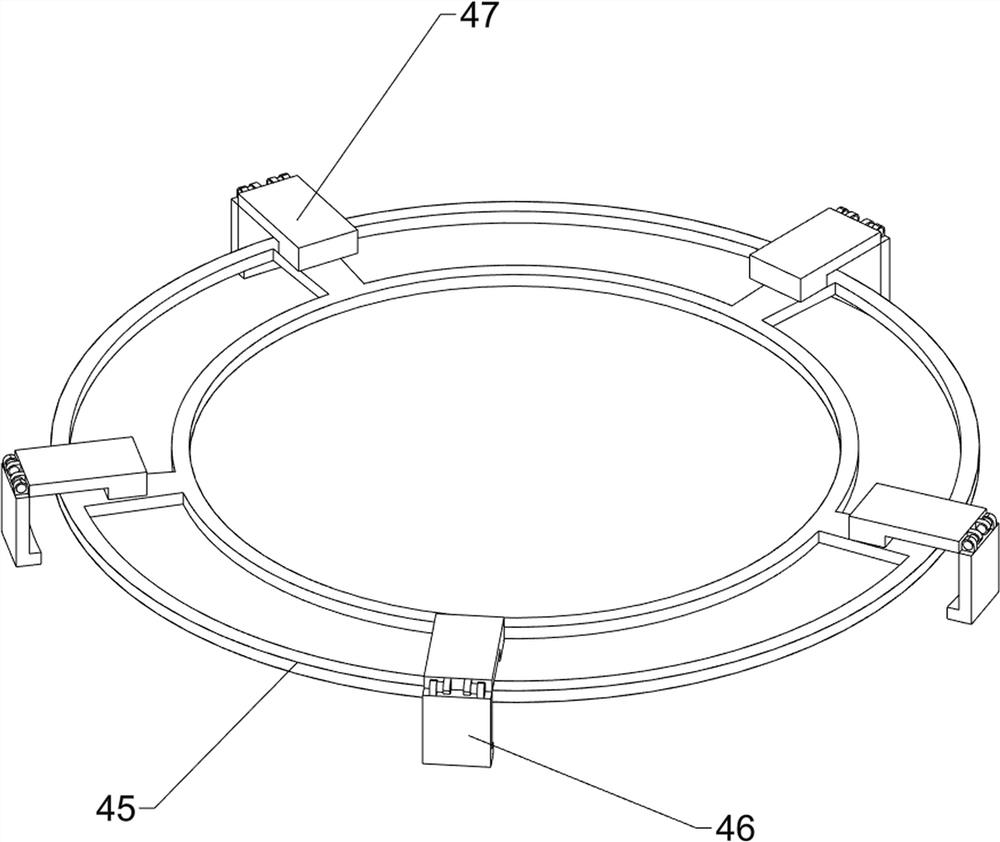
[0025] The clamping device 4 includes a support frame 41, an annular slide rail 42, a fan-shaped slide block 43, a rotating barrel 44, a placement frame 45, a fixed block 46 and a splint 47. The annular slide rail 42 is arranged on the top of the base 1 through the support frame 41, and the ring The axle center of slide rail 42 coincides with the axle center of waste material hopper 3, and fan-shaped slide block 43 is evenly slidably arranged ...

Embodiment 2

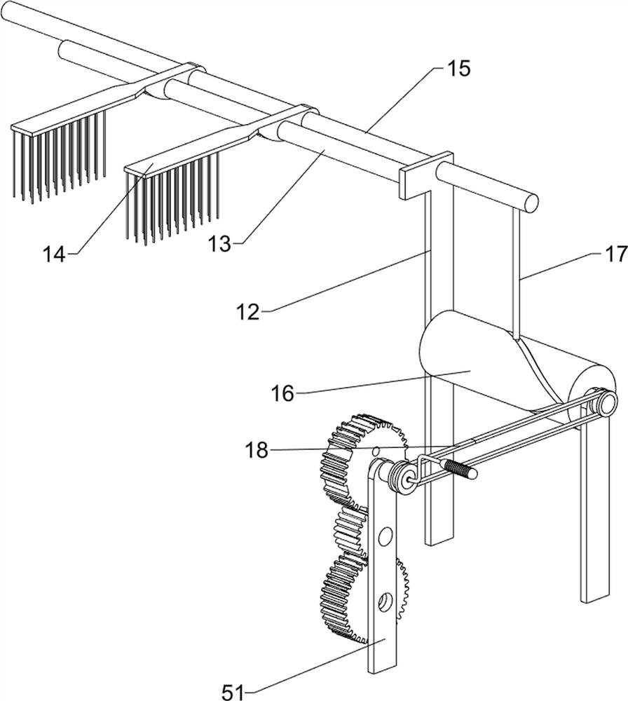
[0029] Such as Figure 5-6 As shown, on the basis of Example 1, a forging device for making iron pots also includes a bearing seat 6, a horizontal shaft 7, a large gear 8, a pinion 9, a vertical shaft 10, a bevel gear 11, and a base 1 The top is located at the position below the placement platform 2 and a bearing seat 6 is provided. A horizontal rotation shaft 7 is rotatably provided between the bearing seat 6 and the lower part of the mounting plate 51 . Pinion 9, pinion 9 meshes with bull gear 8 and missing gear 53 respectively, and the center of the bottom of rotating barrel 44 is provided with vertical shaft 10, and the lower end of vertical shaft 10 passes through placement platform 2 and is connected with base 1 in a rotational manner, and the bottom of vertical shaft 10 is connected with Bevel gears 11 are provided on the left ends of the horizontal rotation shafts 7, and the two bevel gears 11 mesh.

[0030] The staff turns the rocking bar 52, and the rocking bar 52 r...


PUM


Abstract

The invention relates to a forging device, in particular to a forging device for iron pan manufacturing. The forging device for iron pan manufacturing is convenient to operate and capable of automatically turning an iron pan. According to the technical scheme, the forging device for iron pan manufacturing comprises a base, a placement table, a clamping device, and a hammering device. The placementtable is arranged at the top of the base, a waste hopper is arranged at the top of the placement table, the clamping device is arranged at the top of the base and is located over the waste hopper, and the hammering device is arranged at the position, close to the clamping device, of the top of the base. The forging device achieves the effects that operation is convenient and the iron pan can automatically be turned.

Description

technical field [0001] The invention relates to a forging device, in particular to a forging device for making iron pots. Background technique [0002] Iron pots are traditional kitchen utensils for cooking food. They can be divided into pig iron pots and wrought iron pots: pig iron pots are made by melting gray iron and cast in models; Thin, good performance of fast heat transfer. [0003] At present, when a master blacksmith forges an iron pot, he needs high temperature to burn the steel plate until it turns red. The master blacksmith uses large pliers to pull it out of the furnace and press it on the ring-shaped shelf. The big hammer turns the small hammer. You hammer and I hammer. , until the thickness of the pot wall is uniform, and it can be polished and shaped after being easily weighed by hand. [0004] The production of wrought iron pans requires hundreds of times of manual forging, which is time-consuming. Long-term forging can easily cause pain in the craftsman'...

Claims


Application Information

Patent Timeline
Patent Type & Authority Applications(China)
IPC IPC(8): B21J7/06B21J13/08B21J13/00B08B1/00
CPCB21J7/06B21J13/08B21J13/00B08B1/002B08B1/008
Inventor 钟和平
Owner 钟和平
Why Eureka
Try Eureka