Pushing mechanism of mechanical polishing equipment for machining

A technology of mechanical processing and pushing mechanism, applied in machine tools, metal processing equipment, grinding/polishing equipment, etc. suitable for grinding workpiece planes, can solve the problems of sliding, difficult to stabilize workpiece pushing, low stability, etc. The process is stable, the workpiece processing is stable, and the effect of strengthening and fixing

Inactive Publication Date: 2020-11-20
泉州市旺隆工业设计有限公司
View PDF0 Cites 5 Cited by
  • Summary
  • Abstract
  • Description
  • Claims
  • Application Information

AI Technical Summary

Problems solved by technology

[0003] When using the push mechanism to push the workpiece to the designated position for grinding, the positions of the workpiece and the push mechanism are placed in a fixed form. Since the workpiece is usually fixed by the thrust of the cylinder or oil cylinder, its stability is relatively low, and it is easy Sliding occurs during the grinding process. At the same time, during the pushing process of the larger workpiece, it is difficult to push the workpiece stably due to the relatively fixed width of the push.

Method used


Image

  • Pushing mechanism of mechanical polishing equipment for machining
  • Pushing mechanism of mechanical polishing equipment for machining
  • Pushing mechanism of mechanical polishing equipment for machining

Examples


Embodiment 1

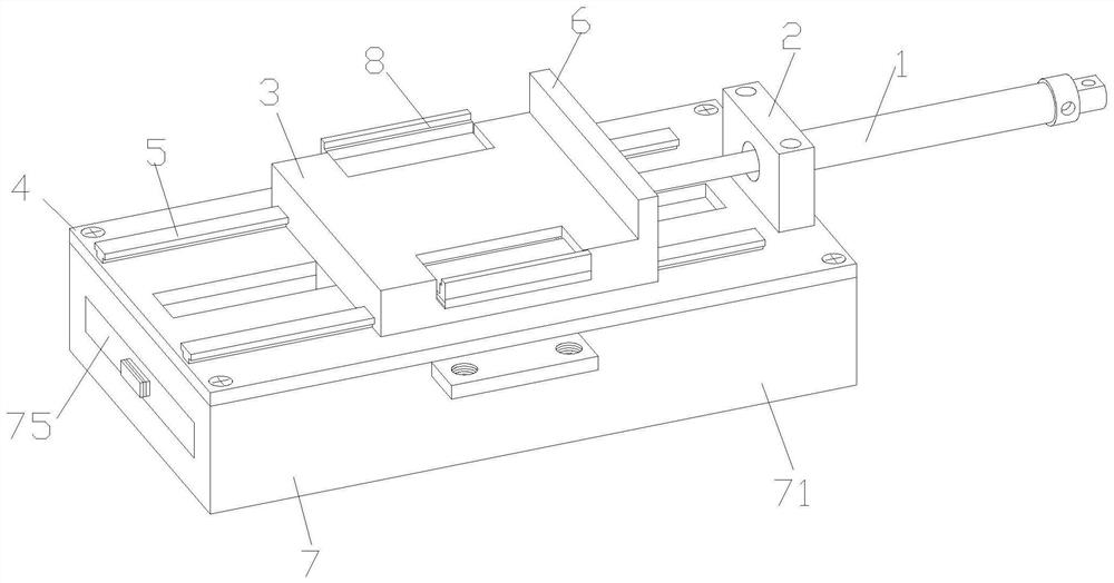
[0030] see figure 1 , the present invention provides a push mechanism for mechanical grinding equipment through improvement, including a cylinder 1 and a side plate 2, the cylinder 1 is installed on the right end side plate 2, and the piston rod on the left side of the cylinder 1 passes through The right end of the side plate 2 is fastened to the top of the right end of the slide plate 3, and the slide plate 3 is slidably mounted on the guide rail 5 fastened to the top end of the bottom plate 4, and the right end of the top of the slide plate 3 is provided with a push plate 6.

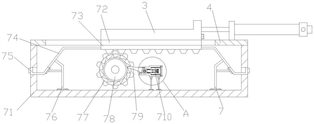
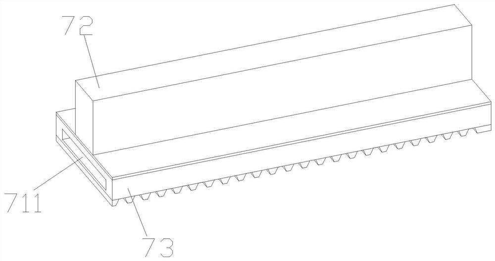
[0031] see figure 2 and image 3, the present invention provides a push mechanism for mechanical grinding equipment through improvement, the auxiliary reinforcement mechanism 7 is arranged on the bottom of the bottom plate 4, the extension mechanism 8 is arranged on the inner side of the slide plate 3, and the auxiliary reinforcement mechanism 7 includes a pre-embedded shell 71. Connecting plate 72,...

Embodiment 2

[0036] The present invention provides a push mechanism for mechanical grinding equipment through improvement. The middle part of the left and right ends of the side plate 2 is provided with a round hole, and the inner diameter of the round hole is 1.5 cm larger than the outer diameter of the output shaft of the cylinder 1. It is convenient to make the output shaft on the left side of the cylinder 1 stably pass through the side plate 2 and connect to the slide plate 3. The guide rail 5 is a T-shaped structure, and the bottom of the slide plate 3 is provided with a matching T-shaped groove, which makes the horizontal movement of the slide plate 3 more stable.

[0037] The present invention provides a push mechanism for mechanical grinding equipment through improvement, and its working principle is as follows;

[0038] First, firstly, the device is fixedly installed on the specified position on the workpiece grinding equipment as a whole, and the embedded shell 71 needs to be fixe...


PUM


Abstract

The invention discloses a pushing mechanism of mechanical polishing equipment for machining. The pushing mechanism comprises an air cylinder, a side plate, a sliding plate, a bottom plate, a guide rail, a pushing plate, an auxiliary reinforcing mechanism and an extending mechanism. According to the pushing mechanism of the mechanical polishing equipment for machining, the auxiliary reinforcing mechanism is arranged at the bottom of the bottom plate, and after a workpiece is driven by the sliding plate to move to a proper position, electrification of an electromagnet can be canceled, so that amovable block drives a clamping plate to move leftwards under elastic force of a micro spring, and the clamping plate is pushed by side surface of a ratchet wheel to slightly rotate and completely enter the position between two gears on the side surface of the ratchet wheel, thus the ratchet wheel and the gears are fixed through the clamping plate, moreover, the positions of a rack, a connecting plate and the sliding plate are fixed through the gears, and the beneficial effects that the sliding plate and the workpiece are further reinforced and fixed, and workpiece machining is more stable areachieved.

Description

technical field [0001] The invention relates to the related field of push mechanisms, in particular to a push mechanism for mechanical grinding equipment used for machining. Background technique [0002] In the daily mechanical processing process, in order to make the surface of some metal plates smooth, it needs to be polished. The existing device for grinding metal plates needs to manually fix the metal plates, and the metal plate workpiece. When transporting to the bottom of the grinding wheel for fixing, at the same time, in order to improve the more comprehensive grinding of the surface of the metal workpiece, it is usually necessary to use a pushing mechanism to transport and fix the workpiece before grinding. [0003] When using the push mechanism to push the workpiece to the designated position for grinding, the positions of the workpiece and the push mechanism are placed in a fixed form. Since the workpiece is usually fixed by the thrust of the cylinder or oil cylin...

Claims


Application Information

Patent Timeline
Patent Type & Authority Applications(China)
IPC IPC(8): B24B7/07B24B41/06B24B41/02B24B55/12B24B41/00B24B47/06
CPCB24B7/07B24B41/005B24B41/02B24B41/06B24B47/06B24B55/12
Inventor 刘斌兴
Owner 泉州市旺隆工业设计有限公司
Why Eureka
Try Eureka