
Method for printing tire mold by using 3D printing technology

A tire mold and 3D printing technology, applied in the field of 3D printing, can solve the problems of material consumption, long printing time, time-consuming and labor-intensive, etc., achieve the effect of clean and hygienic working environment, ensure tire precision, and save labor

Inactive Publication Date: 2020-11-20
泉州市超捷三维科技有限公司
View PDF3 Cites 1 Cited by
  • Summary
  • Abstract
  • Description
  • Claims
  • Application Information

AI Technical Summary

Problems solved by technology

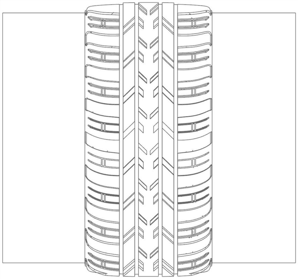
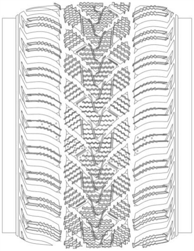
In the traditional method, the steel sheets need to be manually inserted into the pattern grooves of the tire mold one by one, which is time-consuming and laborious, such as figure 2 shown
[0004] The practice of using 3D printers to make tire molds is a manifestation of the progress of an era; but 3D printing is still in the initial stage of exploration in China, and there are very few applications in the tire industry
Moreover, the original tire file is made according to one-eighth of the entire tire (the practice of the entire tire manufacturing industry), because of the overall height, the printing time will be longer; you also need to pay attention when adding support to the tire mold The problem of smoothness; and if the entire one-eighth tire file is printed, it will consume materials; if it is printed directly on a 3D printer, the difficulties that the 3D printer needs to overcome are still difficult to solve, and the size of the upper part of the tire mold is accurate. Degree, shrinkage and other aspects of the data are not satisfactory

Method used

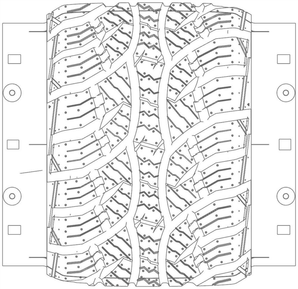

Image

  • Method for printing tire mold by using 3D printing technology
  • Method for printing tire mold by using 3D printing technology
  • Method for printing tire mold by using 3D printing technology

Examples


Embodiment 1

[0038] Such as Figure 3-7 As shown, the present embodiment provides a method for printing a tire mold using 3D printing technology, comprising the following steps:

[0039] 1) Establish a 3D printing model of the tire mold, where the 3D printing model is a traditional 3D printing model, that is, a 3D model built according to one-eighth of the entire tire;

[0040] 2) Using commonly used 3D modeling software, carry out steel sheet modeling in the grooves and pattern grooves of the built 3D printing model, use the original tire 3D printing model, add steel sheet structure to the groove, and upload 3D Printer printing, the printed tire mold directly saves the process of manually adding steel sheets, saves time and effort, and can greatly increase efficiency. After printing, use the cardboard to measure the accuracy;

[0041] 3) Cut the 3D printing model from the middle along the pattern of the tire mold to form two one-sixteenth split tire molds;

[0042] 4) Print two split ti...

Embodiment 2

[0054] This embodiment is an improvement made on the basis of Embodiment 1. The improvements are: in this embodiment, as Figure 8-11As shown, in the step 3), the 3D printing model is cut longitudinally from the middle along the pattern of the tire mold to form two one-sixteenth longitudinal split tire molds; two one-sixteenth tire molds that have been printed The longitudinally split tire molds are each fixed by a master model, and spliced ​​after the casting is completed.

[0055] In this embodiment, the 3D printing model is cut along the longitudinal direction, which can better print the pattern and improve the printing effect.


PUM


Abstract

The invention discloses a method for printing a tire mold by using a 3D printing technology, and relates to the technical field of 3D printing. The method comprises the following steps of 1) establishing a 3D printing model of the tire mold; 2) carrying out steel sheet modeling in the established 3D printing model; 3) cutting the 3D printing model from the middle along the pattern of the tire mold; 4) carrying out tire mold printing on a bottom support through a 3D printer; (5) removing the bottom support below the tire mold after printing is completed, and cleaning the tire mold, and (6) fixing the printed tire mold to a profiling mold, and casting the tire mold. The 3D printing technology has the advantages that the 3D printing technology is used for printing the tire mold, the labor cost and the material cost can be saved, the tire precision can be guaranteed, a sample cannot deform, and the operation is simpler.

Description

technical field [0001] The invention relates to the technical field of 3D printing, in particular to a method for printing tire molds using 3D printing technology. Background technique [0002] In the traditional tire mold manufacturing method, an expensive five-axis engraving machine (hundreds to tens of millions) is required to manufacture tire molds with complex patterns, and the equipment cost is relatively high; and it is made by using a traditional five-axis engraving machine The tire mold is solid, uses more materials, and is very heavy, such as figure 1 shown. [0003] Moreover, tires have many grooves and pattern grooves, all of which require precise dimensions; after the traditional tire mold is manufactured, there is a set of special pallets used to clamp the size of the grooves (the pallets are made by the supplier), and the follow-up It is also necessary to use a special steel sheet inserted into the pattern groove, and then cast the mold. In the traditional ...

Claims


Application Information

Patent Timeline
Patent Type & Authority Applications(China)
IPC IPC(8): B29C33/38
CPCB29C33/3842B29L2031/757
Inventor 吴志平
Owner 泉州市超捷三维科技有限公司
Learn More