Tire and tire mold for tire vulcanizing

A tire mold and tire technology, which is applied in the field of railway freight cars, can solve the problems of poor visual effect of tire surface appearance, etc., and achieve the effect of improving recognition, ensuring attenuation degree, and ensuring recognition effect

Pending Publication Date: 2020-11-20
HIMILE MECHANICAL SCI & TECH (SHANDONG) CO LTD
View PDF0 Cites 1 Cited by
  • Summary
  • Abstract
  • Description
  • Claims
  • Application Information

AI Technical Summary

Problems solved by technology

However, the black tire outer surface thus obtained is also relatively smooth, and this smooth outer surface will form a reflection effect on light, resulting in poor visual effects of the appearance of the tire surface

Method used


Image

  • Tire and tire mold for tire vulcanizing
  • Tire and tire mold for tire vulcanizing
  • Tire and tire mold for tire vulcanizing

Examples


Embodiment 1

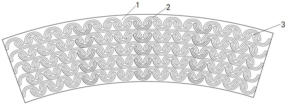
[0056] In a typical embodiment of the present invention, refer to figure 1 and Figure 7 As shown, a tire is equipped with an identification area 1, and the identification area is located on the sidewall of the tire.

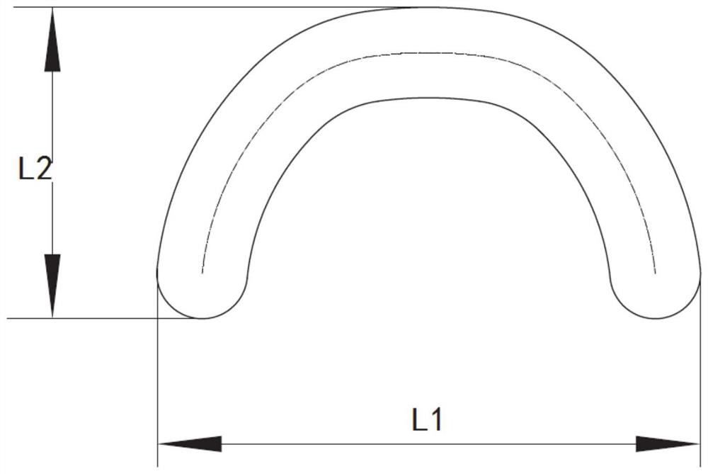
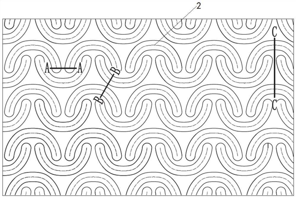
[0057] The marking area 1 has a relatively bright part and a dark part. The dark part is provided with a texture, and the texture protrudes from the outer surface of the tire. The chain 3 includes a plurality of curved portions 2 that protrude from the outer surface of the tire. Two adjacent curved portions 2 of each curved portion chain 3 are arranged at a predetermined distance, and the top end of the curved portion is smaller than the bottom end.

[0058] At least one end of each curved part chain curved part is inserted into the curved inner side of the curved part adjacent to the curved part in the adjacent curved part chain, the curved part is bent, and the direction of the normal line in the curved part is the curved inner side of the curved part, The d...

Embodiment 2

[0071] The differences between this embodiment and Embodiment 1 are:

[0072] refer to Figure 8 As shown, a raised portion 4 is arranged between two adjacent bent portions in each curved portion chain. In some examples, the raised portion is an independent raised portion 4, and the raised portion 4 can be conical or cylindrical. , frustum-shaped, etc., the height of the independent raised part is preferably consistent with the height of the curved part; the setting of the raised part further facilitates the attenuation of light in the curved part chain, and is conducive to the highlighting of the texture.

[0073] All the protrusions in each bending chain are arranged on the same straight line or on the same curve. For the bending chains arranged in rows and columns, the protrusions in two adjacent bending chains arranged at intervals are arranged on multiple straight lines , for a fan-shaped or ring-shaped bent part chain, the protrusions in two adjacent bent part chains ar...

Embodiment 3

[0075] The differences between this embodiment and Embodiment 1 are:

[0076] The curved part is provided with a branch structure, the branch structure is connected to the parent curved part, interspersed in the blank area between the curved parts, the branch structure is connected to the adjacent curved part, the branch structure has a set height, and the height of the branch structure is less than or equal to the curved part the height of.

[0077] The branch structure includes a first connecting portion 5, and / or, also includes a protruding portion 6 disposed inside the bending portion, and / or, also includes a second connecting portion 7 for connecting two bending portions in two adjacent bending portion chains .

[0078] Specifically, in some examples, refer to Figure 9 and Figure 10 As shown, the adjacent bending parts of the same bending part chain are connected by the first connecting part 5, the number of the first connecting part is 1-3, and the interval between ...


PUM

PropertyMeasurementUnit
lengthaaaaaaaaaa

Abstract

The invention discloses a tire and a tire mold for tire vulcanizing. The problem that the outer surfaces of tires in the prior art are smooth and strong in reflection, and then the visual effect of amarking area is poor is solved, and the beneficial effect of improving the recognition of the tire marking area is achieved. The specific scheme is as follows: the tire includes a marking area, the marking area is provided with a dark part, and the dark part is provided with textures; the textures include a plurality of curved part chains; the plurality of curved part chains are arranged in a setmanner; each curved part chain includes a plurality of curved parts protruding from the outer surface of the tire; the curved parts of every two adjacent curved part chains are arranged in opposite curve directions and arranged in a staggered mode; and at least one end of each curved part of each curved part chain is inserted into the curved inner side of the adjacent curved part in the adjacent curved part chain.

Description

technical field [0001] The invention relates to the field of railway wagons, in particular to a tire and a tire mold used for vulcanizing the tire. Background technique [0002] The statements in this section merely provide background information related to the present invention and do not necessarily constitute prior art. [0003] There are a large number of patterns, fonts and other marks on the sidewall of the tire. These marks are made through a tire mold, and a groove structure is provided on the surface of the tire mold, and a corresponding stripe structure is obtained on the tire surface by vulcanization. [0004] The inventors have found that usually the tire vulcanization mold is made of metal, and the surface of the tire mold is usually relatively smooth after processing, with a high degree of smoothness. However, the obtained black tire outer surface is also relatively smooth, and this smooth outer surface will reflect light, resulting in a poor visual effect of...

Claims


Application Information

Patent Timeline
Patent Type & Authority Applications(China)
IPC IPC(8): B29C33/42B29D30/06B29L30/00
CPCB29C33/424B29D30/0606B29D2030/0616B29L2030/00
Inventor 李承霖孙日文张伟王磊
Owner HIMILE MECHANICAL SCI & TECH (SHANDONG) CO LTD
Why Eureka
Try Eureka