Color inkjet device for textile yarn

A color inkjet and yarn technology, applied in printing, typewriter and other directions, can solve the problems of cumbersome process, low efficiency, superimposition of different colors or large separation distance, etc., to achieve recycling, improve sealing and uniformity Good results

Pending Publication Date: 2020-11-20
无锡市德赛数码科技有限公司
View PDF0 Cites 1 Cited by
  • Summary
  • Abstract
  • Description
  • Claims
  • Application Information

AI Technical Summary

Problems solved by technology

[0002] In the prior art, most of the inkjet devices for textile yarns can only jet a single color of ink. If color printing is required, the ink in the inkjet assembly must be replaced, and then the overlaying and coloring will be completed after multiple threads. The process is cumbersome, the efficiency is low, and the inkjet positions and ranges of different colors of ink are not accurately controlled, resulting in the superimposition of different colors or too large separation distances, which cannot meet the inkjet needs of yarns.
[0003] In addition, in the prior art, the ink for jet printing is usually directly ejected from the nozzle, and the ejected ink droplets are in the shape of droplets, forming droplet-shaped ink spots on the yarn, which is not aesthetically pleasing, so in order to further optimize the ink Spot shape, requiring improvements to inkjet components

Method used


Image

  • Color inkjet device for textile yarn
  • Color inkjet device for textile yarn
  • Color inkjet device for textile yarn

Examples


Embodiment Construction

[0025] The specific implementation manner of the present invention will be described below in conjunction with the accompanying drawings.

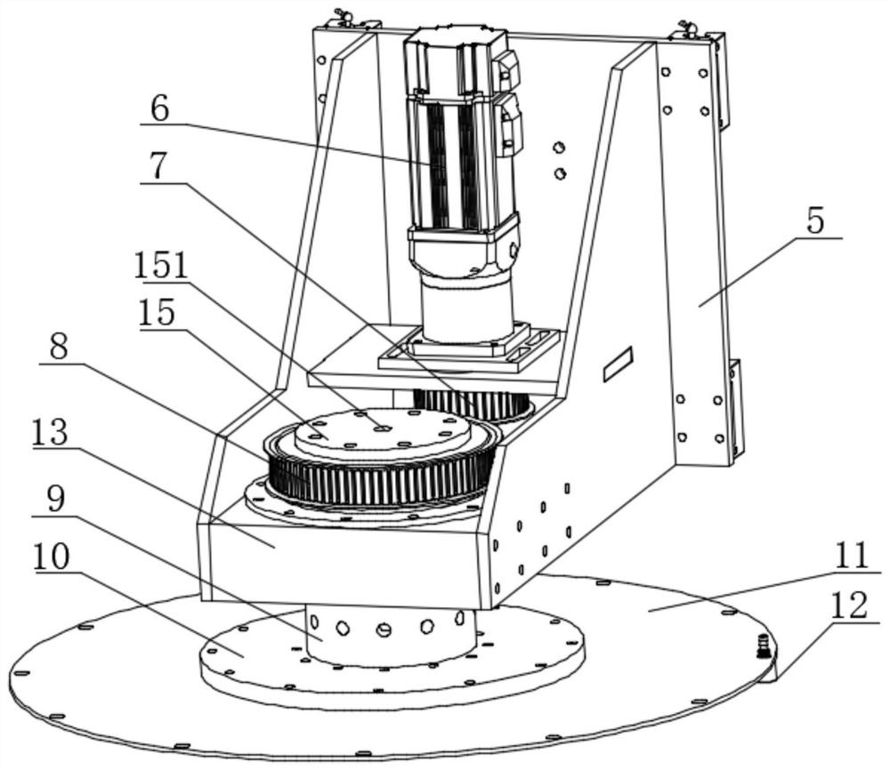
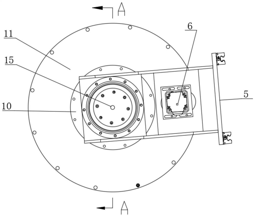
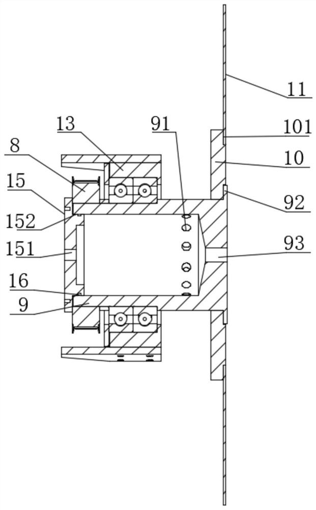
[0026] Such as Figure 5 , Figure 1-Figure 3 As shown, it includes multiple groups of rotary nozzle assemblies, and multiple groups of rotary nozzle assemblies are arranged at intervals along the direction of the yarn. Each group of rotary nozzle assemblies has the same structure, including a sliding support 5, which moves up and down in the vertical direction, The sliding support 5 is equipped with a rotary shaft 9 through a bearing box 13. The rotary shaft 9 is a cylindrical structure with an open top and a hollow cavity inside. The top of the rotary shaft 9 is provided with a cover plate 15 that closes the hollow cavity. The lower part is provided with a plurality of liquid outlet holes 91 along the circumference, and the bottom of the rotary shaft 9 is connected with a rotary disc 11 with an enlarged diameter. The circumference of th...


PUM


Abstract

The invention relates to a color inkjet device for a textile yarn. The device comprises multiple sets of rotating nozzle assemblies. The rotating nozzle assemblies are arranged at intervals along thedirection of the yarn. Each set of rotating nozzle assemblies has the same structure, and comprises a sliding support. The sliding support moves up and down in the vertical direction. A rotary shaft is installed in the sliding support through a bearing box. The rotary shaft is a columnar structure with an opening at the top and a hollow cavity inside. The top of the rotary shaft is provided with acover plate. The cover plate closes the hollow cavity. The lower part of the rotary shaft is provided with a plurality of liquid outlet holes along the circumferential direction. The bottom of the rotary shaft is connected with a rotary disc with a larger diameter. The circumference of the rotary disc is provided with a plurality of nozzle installation holes for installing nozzles. The positionsof the nozzles correspond to the positions of the liquid outlet holes one to one. The device has the function of multi-color jet printing so as to realize the color inkjet of the yarn, and at the sametime, the device can form dot-like or mist-like ink spot patterns as required to meet the inkjet requirements of different products.

Description

technical field [0001] The invention relates to the technical field of yarn coloring devices, in particular to a color inkjet device for textile yarns. Background technique [0002] In the prior art, most of the inkjet devices for textile yarns can only jet a single color of ink. If color printing is required, the ink in the inkjet assembly must be replaced, and then the overlaying and coloring will be completed after multiple threads. The process is cumbersome, the efficiency is low, and the inkjet positions and ranges of different colors of inks are not accurately controlled, resulting in the superimposition of different colors or too large separation distances, which cannot meet the inkjet needs of yarns. [0003] In addition, in the prior art, the ink for jet printing is usually directly ejected from the nozzle, and the ejected ink droplets are in the shape of droplets, forming droplet-shaped ink spots on the yarn, which is not aesthetically pleasing, so in order to furt...

Claims


Application Information

Patent Timeline
Patent Type & Authority Applications(China)
IPC IPC(8): B41J2/21B41J2/17B41J2/175B41J3/407
CPCB41J2/2103B41J2/17503B41J2/1721B41J3/4078B41J2/175
Inventor 岳双君
Owner 无锡市德赛数码科技有限公司
Why Eureka
Try Eureka