Paddle leg composite driving mechanism

A driving mechanism and paddle leg technology, applied in the field of driving mechanism, can solve the problems of low operation efficiency, slow speed, difficulty in meeting land obstacle crossing and underwater propulsion requirements at the same time, etc., and achieve high travel speed, long service life, and high terrain. adaptive effect

Active Publication Date: 2020-11-20
HARBIN INST OF TECH
View PDF5 Cites 2 Cited by
  • Summary
  • Abstract
  • Description
  • Claims
  • Application Information

AI Technical Summary

Problems solved by technology

[0004] The present invention aims to solve the problems of low operating efficiency and slow speed of the existing amphibious hexapod robot driving device, and it is difficult to meet the requirements of land obstacle surmounting and underwater propulsion at the same time.

Method used


Image

  • Paddle leg composite driving mechanism
  • Paddle leg composite driving mechanism
  • Paddle leg composite driving mechanism

Examples


specific Embodiment approach 1

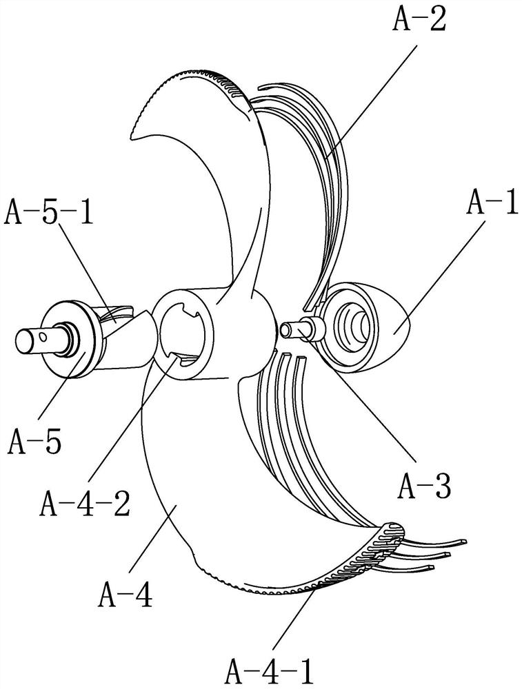
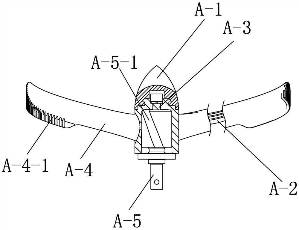
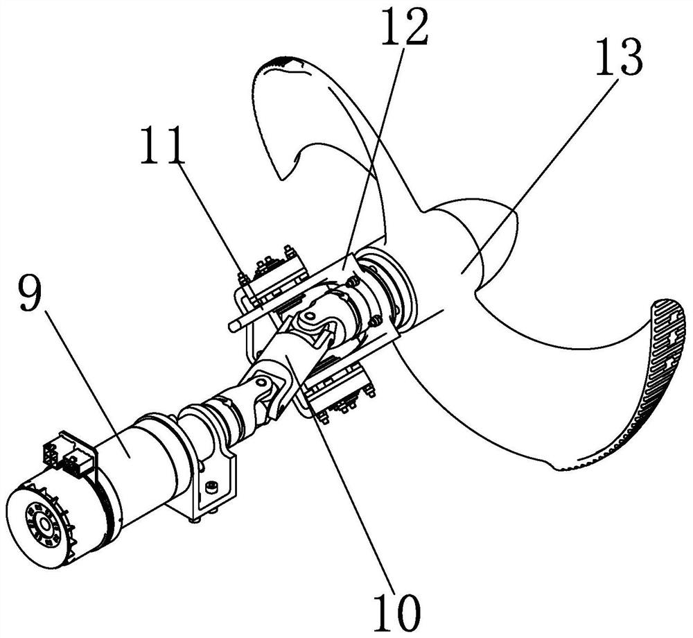
[0019] Specific implementation mode one: combine Figure 1 to Figure 4 To illustrate this embodiment, a paddle leg composite driving mechanism in this embodiment includes a paddle leg drive module and a paddle leg 13, and the paddle leg 13 includes a conical cap A-1, an embedded beam A-2, a fixing screw A-3, a paddle leg The leg base A-4 and the screw shaft A-5, the screw shaft A-5 is provided with a spiral groove A-5-1, the screw shaft A-5 is inserted in the paddle leg base A-4 and rotated by the fixing screw A-3 into the screw hole of the screw shaft A-5, the embedded beam A-2 is embedded in the paddle leg base A-4, and one end of the embedded beam A-2 extends into the screw tenon A-5-1, and the cone cap A-1 is installed on the circular platform protrusion outside the hub of the paddle leg base A-4; the paddle leg base A-4 is a C-shaped propeller blade, and the cone cap A-1 and the paddle leg base A-4 are made of flexible material, the paddle leg drive module is connected w...

specific Embodiment approach 2

[0023] Specific implementation mode two: combination Figure 1 to Figure 2 To describe this embodiment, both the conical cap A-1 and the paddle leg base A-4 of this embodiment are made of thermoplastic polyurethane rubber material. With such a setting, it is very flexible and wear-resistant. It is suitable for walking on land and overcoming obstacles. It can withstand ground wear for a long time and has a long service life. It can be divided into two halves by using the helical surface as the parting surface and made by mold overmolding. The cone cap A-1 can also be made by 3D printing by fused deposition and direct mold overmolding. Other compositions and connections are the same as in the first embodiment.

specific Embodiment approach 3

[0024] Specific implementation mode three: combination Figure 1 to Figure 2 To describe this embodiment, a plurality of grooves A-4-1 are provided along the axial direction on the outer end surface of the C-shaped propeller blade of the paddle leg base A-4 of this embodiment. Such setting is convenient for the propeller blade to increase the frictional force of the ground or water body when rotating. Other compositions and connections are the same as those in Embodiment 1 or Embodiment 2.


PUM


Abstract

The invention discloses a paddle leg composite driving mechanism, and relates to a driving mechanism. The invention solves the problems that an existing amphibious hexapod robot driving device is lowin operation efficiency and low in speed, and the requirements for land obstacle crossing and underwater propelling are difficult to meet at the same time. A spiral groove (A-5-1) is formed in a spiral shaft (A-5); the spiral shaft (A-5) is inserted into a propeller leg base body (A-4) and screwed into a screw hole of the spiral shaft (A-5) through a fixing screw (A-3); an embedded beam (A-2) is embedded into the propeller leg base body (A-4); one end of the embedded beam (A-2) extends into a spiral tenon (A-5-1), and a conical cap (A-1) is mounted on a truncated cone protrusion outside the hub of the propeller leg base body (A-4) ; the propeller leg base body (A-4) is a C-shaped propeller blade, the conical cap (A-1) and the propeller leg base body (A-4) are both made of flexible wear-resistant materials, and a propeller leg driving module is connected with the spiral shaft (A-5). The mechanism is used for amphibious hexapod robots.

Description

technical field [0001] The invention relates to a driving mechanism, in particular to a driving mechanism which is compounded with a propeller and a C-shaped leg in appearance, has flexibility in mechanical properties, and can artificially adjust the stiffness, and belongs to the field of land walking devices and water surface or underwater propulsion devices . Background technique [0002] With the increasing demand for scientific investigation, resource exploration and development, disaster rescue and treatment, and military operations in complex environments, the development and application of robots that can operate in complex environments, especially amphibious robots, has become a key research field one. At present, the amphibious robots studied at home and abroad have limitations. These robots can be roughly divided into two types: one is based on separate water and land drive mechanisms, which either require manual replacement of the drive mechanism or require a com...

Claims


Application Information

Patent Timeline
Patent Type & Authority Applications(China)
IPC IPC(8): B60F3/00
CPCB60F3/0007
Inventor 张赫卢光正赵杰
Owner HARBIN INST OF TECH
Why Eureka
Try Eureka