Rail hand-cranking sightseeing vehicle

A technology for sightseeing cars and tracks, applied in the field of rail sightseeing cars, can solve the problems of lack of tourist fun and inconvenience in electricity consumption, and achieve the effects of avoiding excessive speed, improving efficiency and obvious deceleration effect.

Active Publication Date: 2020-11-20
浙江天佑铁路设备科技有限公司
View PDF6 Cites 3 Cited by
  • Summary
  • Abstract
  • Description
  • Claims
  • Application Information

AI Technical Summary

Problems solved by technology

[0004] In order to overcome the problem that the rail sightseeing cars in the scenic spots in the prior art are generally driven by electricity, which has the problem of inconvenient power consumption, and lacks the fun of tourists doing it by themselves, the present invention provides a rail hand-operated sightseeing car, which can be used by shaking The rocker can drive the sightseeing car to move forward smoothly on the track. It is easy to operate, does not require power supply, and can increase the fun of sightseeing.

Method used


Image

  • Rail hand-cranking sightseeing vehicle
  • Rail hand-cranking sightseeing vehicle
  • Rail hand-cranking sightseeing vehicle

Examples


Embodiment 1

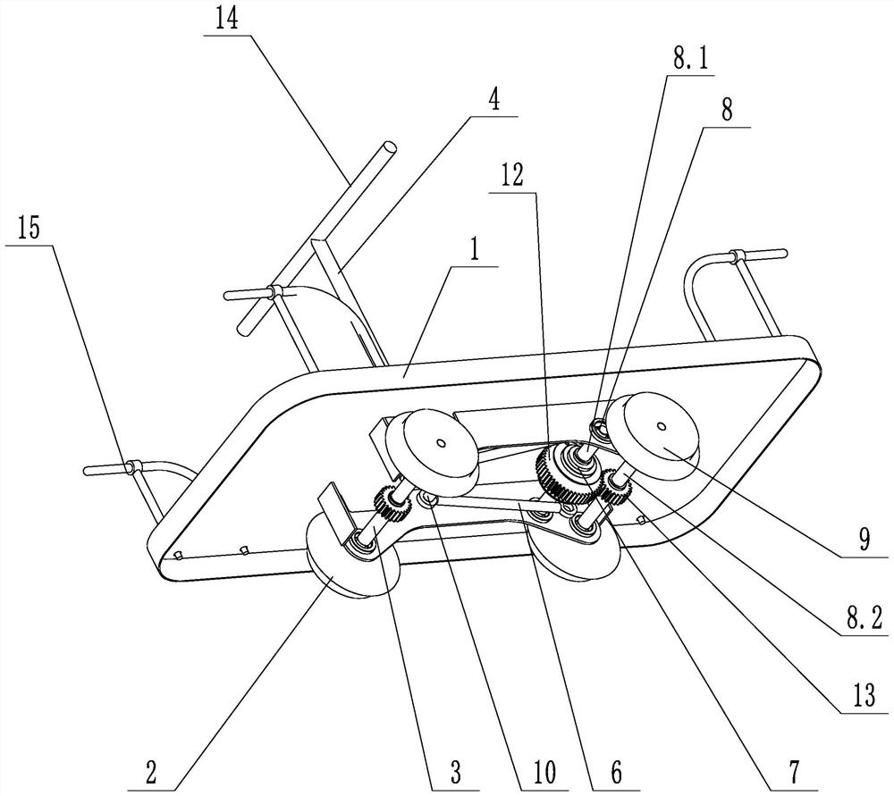
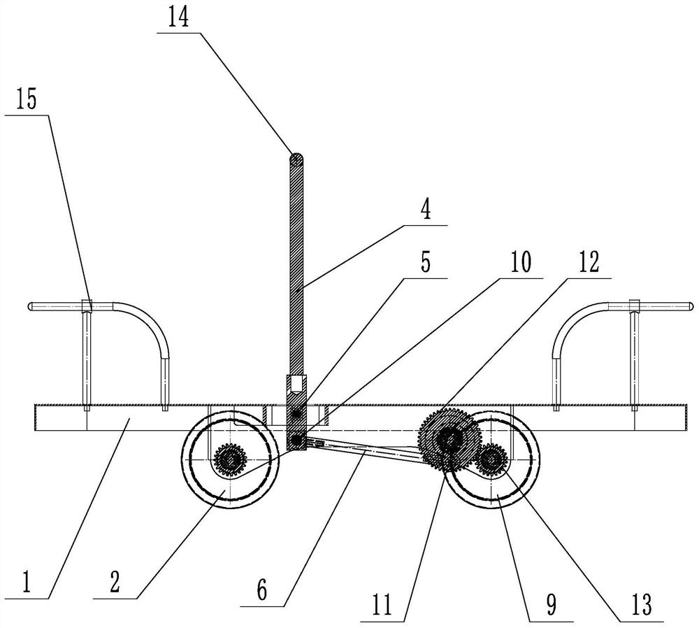
[0027] like figure 1 and figure 2 shown ( figure 1 The second pin shaft 11 is not shown), a rail hand sightseeing car, including a platen 1, a front wheel 2, a front wheel shaft 3, a rocker 4, a first rotating shaft 5, a connecting rod 6, a ratchet mechanism 7, a Second rotating shaft 8, rear wheel 9, driving gear 12 and driven gear 13, the diameter of driving gear 12 is greater than driven gear 13; , the rear wheel shaft 8.2 is rotationally connected with the platen 1; the driving gear 12 and the ratchet mechanism 7 are fixed on the transition shaft 8.1, the rear wheel 9 and the driven gear 13 are fixed on the rear wheel shaft 8.2, and the driving gear 12 meshes with the driven gear 13; The wheel 2 is rotationally connected with the platen 1 through the front axle 3, the rocking bar 4 is rotationally connected with the platen 1 through the first rotating shaft 5, the upper end of the rocking bar 4 is provided with a handle 14, and the lower end of the rocking bar 4 is conn...

Embodiment 2

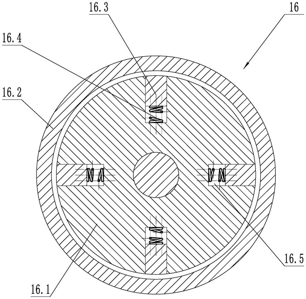
[0030] like image 3 As shown, on the basis of Embodiment 1, a speed-limiting mechanism 16 is also included. The speed-limiting mechanism 16 includes a rotating wheel 16.1, a friction wheel cover 16.2, a friction block 16.3 and a telescopic spring 16.4, and the rotating wheel 16.1 is coaxially fixed with the front wheel shaft 3 , the front axle 3 is provided with a chute 16.5 arranged radially, the friction block 16.3 is slidably connected with the rotating wheel 16.1 through the chute 16.5, one end of the telescopic spring 16.4 is connected with the friction block 16.3, and the other end of the telescopic spring 16.4 is connected with the rotating wheel 16.1 The friction wheel cover 16.2 is fixed to the platen 1, and the friction wheel cover 16.2 is coaxially arranged with the rotating wheel 16.1, and the friction block 16.3 contacts with the inner side wall of the friction wheel cover 16.2 when extending out.

[0031]The speed limiting mechanism 16 can play a very good role ...

Embodiment 3

[0033] like Figure 4 As shown, on the basis of Embodiment 1, a brake mechanism 17 is also included. The brake mechanism 17 includes a brake pad 17.1, a connecting block 17.2, a brake spring 17.3, a brake disc 17.4, a connecting rod 17.5 and a hand brake lever 17.6; The plate 1 is connected in rotation, the hand brake lever 17.6 is fixed to the upper end of the connecting rod 17.5, the brake disc 17.4 is fixed to the lower end of the connecting rod 17.5, the connecting block 17.2 is slidingly connected to the platen 1, one end of the connecting block 17.2 is fixed to the brake pad 17.1, and the connecting block The other end of 17.2 is in contact with brake disc 17.4; the section of brake disc 17.4 is oval; one end of brake spring 17.3 is connected with platen 1, and the other end of brake spring 17.3 is connected with connecting block 17.2. The number of the brake pads 17.1, connecting blocks 17.2 and brake springs 17.3 is 2 respectively, and the brake pads 17.1, connecting b...


PUM


Abstract

The invention discloses a rail hand-cranking sightseeing vehicle which comprises a platen, front wheels, a front wheel shaft, a rocker, a first rotating shaft, a connecting rod, a ratchet mechanism, asecond rotating shaft and rear wheels. The front wheels are rotatably connected with the platen through the front wheel shaft; the rocker is rotatably connected with the platen through the first rotating shaft, and a lower end of the rocker is hinged with one end of the connecting rod through a first pin shaft; the ratchet mechanism comprises an inner wheel and an outer wheel, the inner wheel andthe second rotating shaft are coaxially fixed, a second pin shaft is eccentrically arranged on the outer wheel, and the other end of the connecting rod is hinged to the outer wheel through the secondpin shaft; and the rear wheel is fixed with a second rotating shaft which is rotatably connected with the platen. According to the rail hand-cranking sightseeing vehicle, the rocker can be rocked todrive the sightseeing vehicle to stably move forwards on a rail, operation is convenient, a power source is not needed, and sightseeing pleasure can be increased.

Description

technical field [0001] The invention relates to the field of rail sightseeing cars, in particular to a rail hand-operated sightseeing car. Background technique [0002] There are often rail sightseeing cars in domestic scenic spots. Tourists can visit according to the prescribed routes. The rail sightseeing cars in existing scenic spots are generally driven by electricity, or use batteries for power supply. In this way, the mileage of the batteries affects the sightseeing cars. The use of cables, or the use of cable power supply, there is a risk of leakage in this way, and the electric drive tour bus lacks the fun of tourists doing it themselves. Therefore, it is necessary to design a hand-cranked sightseeing car on a track, which can drive the sightseeing car to move forward steadily on the track by shaking the rocker. It is easy to operate, does not need a power supply, and can increase the fun of sightseeing. [0003] Chinese Patent Application Publication No. CN10289718...

Claims


Application Information

Patent Timeline
Patent Type & Authority Applications(China)
IPC IPC(8): B61D15/00B61H7/12
CPCB61D15/00B61H7/12
Inventor 徐新建严鑫徐新印毛淑文王庆
Owner 浙江天佑铁路设备科技有限公司
Why Eureka
Try Eureka