High-stability underground coal mine inspection robot

An inspection robot and high-stability technology, applied in the field of robots, can solve the problem that the crawler wheels cannot be adjusted according to the terrain of up and down slopes, and achieve the effect of improving the climbing ability, good stability, and easy to climb uphill.

Inactive Publication Date: 2020-11-20
张铭元
View PDF6 Cites 4 Cited by
  • Summary
  • Abstract
  • Description
  • Claims
  • Application Information

AI Technical Summary

Problems solved by technology

[0005] The purpose of the present invention is to solve the above problem that the crawler wheels cannot be adjusted according to the uphill and downhill terrain, and to provide a highly stable coal mine underground inspection robot that can adjust the crawler wheels according to the uphill and downhill terrain.

Method used


Image

  • High-stability underground coal mine inspection robot
  • High-stability underground coal mine inspection robot
  • High-stability underground coal mine inspection robot

Examples


Embodiment 1

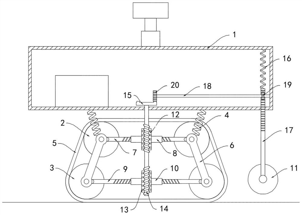
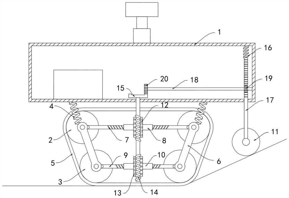
[0018] Such as Figure 1-2 As shown, a high-stability coal mine underground inspection robot includes a car body 1, a driving motor is installed on the lower surface of the car body 1, a driving wheel is installed on the output shaft of the driving motor, and upper and lower sides of the driving wheel are provided. Driven wheel 2, two upper driven wheels 2 are rotationally connected with car body 1 by supporting spring 4 respectively, two lower driven wheels 3 are arranged below the two upper driven wheels 2, driving wheel, upper driven wheel 2 and lower driven wheel 3 are connected by crawlers 5, and the upper driven wheel 2 and the lower driven wheel 3 are connected by connecting rod 6. The upper ends of the two connecting rods 6 are connected with upper threaded rods 7, and the two upper threaded rods 7 are threaded on the surface. The screw direction is opposite, and the external threads of two upper threaded rods 7 are socketed with an upper threaded cylinder 8, and the l...

Embodiment 2

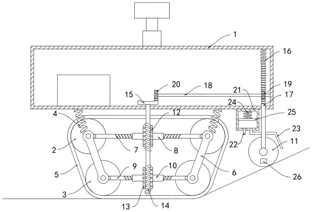
[0024] Such as image 3 As shown, the difference between this embodiment and Embodiment 1 is: the bottom surface of the car body 1 is fixedly equipped with a wrecker box 21, and the side wall of the wrecker box 21 is fixedly connected with a one-way air intake pipe 22 and a one-way exhaust pipe. Pipe 23, the one-way air intake pipe 22 only allows outside air to enter the obstacle removal box 21, the one-way exhaust pipe 23 only allows the air in the obstacle removal box 21 to be discharged, and the lower end of the one-way exhaust pipe 23 extends to the detection wheel 11 Set at the location, the piston plate 25 is sealed and slidably connected in the obstacle removal box 21, the piston plate 25 is made of ferromagnetic material, the upper surface of the piston plate 25 is fixedly connected with the inner top surface of the obstacle removal box 21 by the return spring 24, and the detection wheel The sidewall of 11 is equipped with permanent magnet piece 26.

[0025] In this e...


PUM


Abstract

The invention belongs to the technical field of robots and relates to a high-stability underground coal mine inspection robot. A vehicle body is included. A driving motor is mounted on a lower surfaceof the vehicle body; a driving wheel is mounted on an output shaft of the driving motor; upper driven wheels are arranged on the two sides of the driving wheel correspondingly; the two upper driven wheels are rotatably connected with the vehicle body through supporting springs correspondingly; and two lower driven wheels are arranged below the two upper driven wheels, the driving wheel, the upperdriven wheels and the lower driven wheels are connected through crawler belts, the upper driven wheels and the lower driven wheels are rotatably connected through connecting rods, and upper threadedrods are rotatably connected to the upper ends of the two connecting rods. A horizontal distance between the upper driven wheels and the lower driven wheels can be changed so as to adapt to uphill anddownhill road conditions, the inspection robot can climb uphill conveniently, meanwhile, a possibility that the inspection robot turns over on a steep downhill road section is reduced, stability is better, and smooth implementation of underground coal mine inspection work is facilitated.

Description

technical field [0001] The invention belongs to the technical field of robots, and in particular relates to a high-stability coal mine underground inspection robot. Background technique [0002] With the development and progress of intelligent science and technology, in order to improve the safety of coal mine inspection operations and reduce the labor intensity of staff, more and more inspection robots are put into use in coal mine underground operations. [0003] In order to adapt to the complex terrain and environment of coal mines, most inspection robots use crawler wheels to reduce the range of bumps and shakes when moving forward, which is convenient for inspection and shooting. However, the road surface of coal mines is not smooth, and there are mostly uphill and downhill sections. , while the crawler wheel structure of the traditional inspection robot cannot be adjusted according to the uphill and downhill sections, which makes it difficult for the traditional inspec...

Claims


Application Information

Patent Timeline
Patent Type & Authority Applications(China)
IPC IPC(8): B62D55/084B62D55/116E01H1/00E01H1/08
CPCB62D55/084B62D55/116E01H1/005E01H1/0809
Inventor 张铭元
Owner 张铭元
Why Eureka
Try Eureka