
Patsnap Eureka
For R&D, Patsnap Eureka makes reading and utilizing patents & technical documents easy.
Patsnap Eureka AIR
Designed for self-driven R&D workflows. Generate viable solutions, solve complex R&D challenges, empower your innovation with AI.

Patsnap Eureka Materials
Designed for material experts only. Revolutionize your material R&D, from search, analyze, to developing new materials.

TechResearch
Generate reliable direction feasibility study reports for your R&D in just a few steps.

TechSeek
Discover and master advanced knowledge NOW. Basics, ideas, possibilities, all at once.

TechMind
As an expert in R&D Theories, TechMind can generates customized viable solutions instantly.

TechRisk
Analyze your overall solution with one click, know your potential R&D risks in advance.

TechMonitor
Get weekly tech updates, stay abreast of the latest tech innovations and key insights.
Novel hydraulic oil heat dissipation device
A technology of heat dissipation device and hydraulic oil, which is applied in the direction of fluid pressure actuation device, fluid pressure actuation system components, mechanical equipment, etc., can solve the problems of low heat dissipation efficiency and can not meet the needs of construction machinery, and achieve cost reduction and improvement space. Utilization, the effect of avoiding power loss
- Summary
- Abstract
- Description
- Claims
- Application Information
AI Technical Summary
Problems solved by technology
Method used
Image

Examples
Embodiment Construction
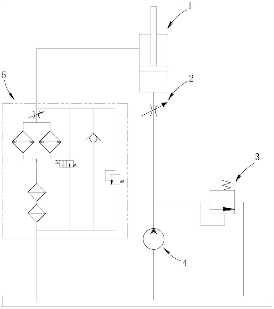
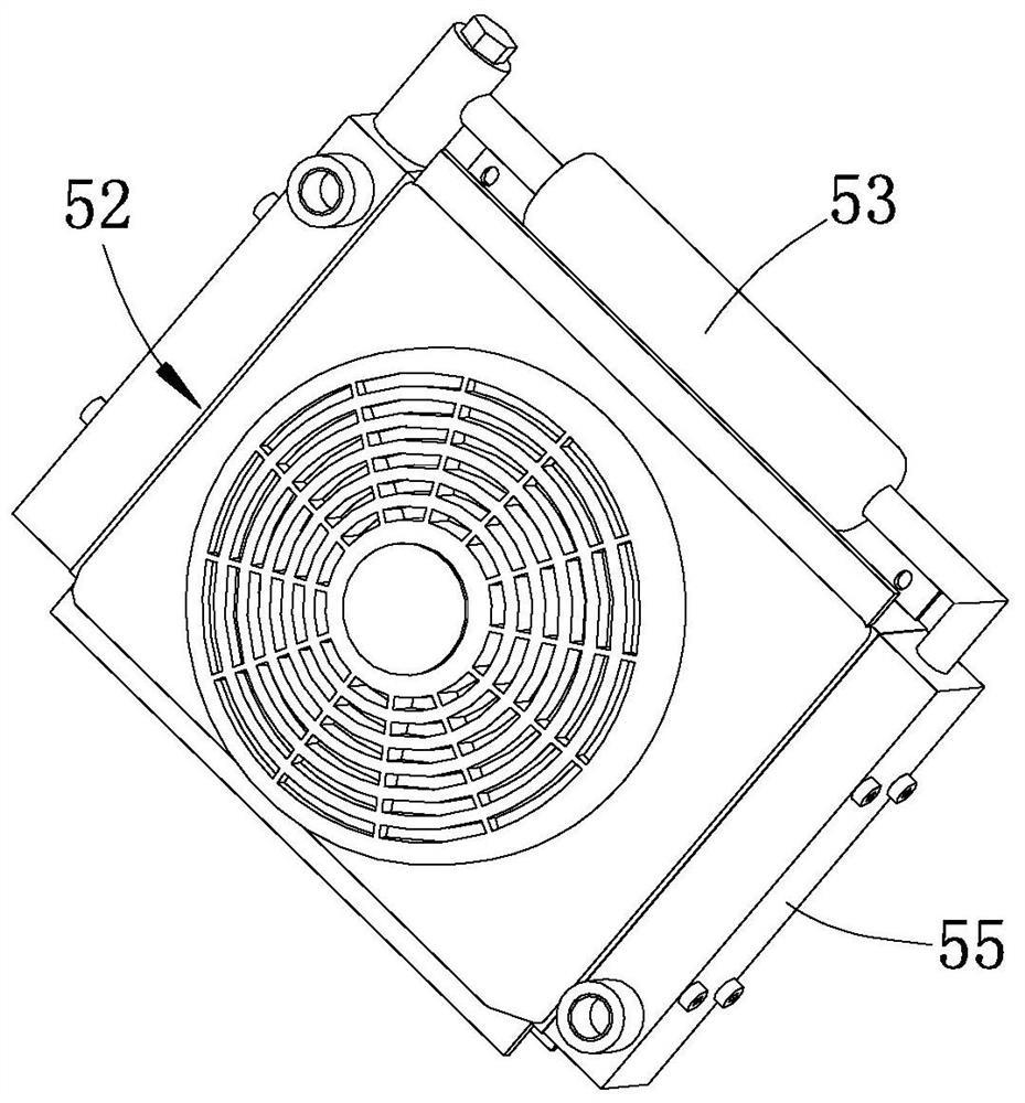
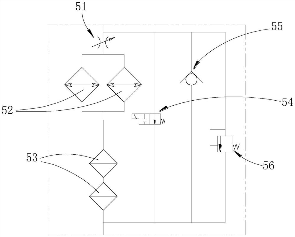
[0021] like Figures 1 to 3 shown
[0022] The novel hydraulic oil cooling device 5 includes a built-in check valve 55, an air-cooled cooling part, a hydraulic filtering part, a throttle valve 51, a solenoid valve 54 and a safety valve 56. The hydraulic filtering part, the air cooling The heat dissipation part, the built-in check valve 55 and each component adopt an integrated one-piece structure ( figure 2 Can only show the radiator 52 of an air-cooled radiating part and the filter element 53 of a hydraulic filter part, and its back side also has a radiator 52 and filter element 53).
[0023] The air-cooled heat dissipation part and the hydraulic filter part constitute the main channel for heat dissipation and filtration of the oil supply liquid. The air-cooled heat dissipation part includes two radiators 52, and the two radiators 52 are arranged in parallel. The device 52 is also provided with a fan, and the air outlet of the fan is aimed at the air-cooled heat sink.
[...
PUM
 Abstract
Description
Claims
Application Information
 - R&D Engineer
- R&D Manager
- IP Professional
- Industry Leading Data Capabilities
- Powerful AI technology
- Patent DNA Extraction
Browse by: Latest US Patents, China's latest patents, Technical Efficacy Thesaurus, Application Domain, Technology Topic, Popular Technical Reports.
© 2024 PatSnap. All rights reserved.Legal|Privacy policy|Modern Slavery Act Transparency Statement|Sitemap|About US| Contact US: help@patsnap.com