Biomass combustion furnace

A technology of biomass combustion furnace and combustion furnace, which is applied in the direction of combustion equipment, solid fuel combustion, lighting and heating equipment, etc. It can solve the problems of waste of resources and waste of biomass fuel, and achieve the effect of improving heat conversion efficiency

Active Publication Date: 2020-11-20
HENAN UNIV OF URBAN CONSTR
9 Cites 1 Cited by

AI-Extracted Technical Summary

Problems solved by technology

[0003] The hearth of the biomass burning furnace is mostly long cylindrical. When people use it, they will add biomass fuel to the furnace every time they see that the fuel in the burning furnace is about to burn out. In order to avoid repeated operations, they often add ...

Method used

As shown in Figure 3, the bottom of the combustion furnace body 1 is fixedly connected with the ventilation plate 15 with a corrugated shape, and the ventilation plate 15 has a plurality of grids 151, and the existing combustion furnace body 1 is provided with a drawer at its bottom , the burnt fuel will turn into powder and leak into the drawer from the grids on the lower end surfaces of the first furnace 2 and the second furnace 9, and the drawer also plays a role in ventilation. In this embodiment, in the combustion furnace body 1 A ventilation plate 15 with a wavy shape is arranged at the bottom, which can increase the air intake volume of the first furnace 2 and the second furnace 9, so that the fuel at the bottom can be burned more fully, so that the biomass fuel can be fully utilized, and at the same time, the heat conversion efficiency. As shown in Fi...

Abstract

The invention relates to the technical field of combustion fuel heating equipment, and discloses a biomass combustion furnace. The biomass combustion furnace comprises a combustion furnace body, a first hearth, a telescopic mechanism, a push plate, a second hearth, a push-pull mechanism, a partition plate and a baffle plate. The first hearth is a square cylinder and is vertically arranged in the combustion furnace body, the telescopic mechanism is perpendicular to the axial direction of the combustion furnace body and arranged between the combustion furnace body and the first hearth, and extends in the horizontal direction, the push plate is vertically arranged, the portion, fixedly connected with the telescopic end of the telescopic mechanism, of the push plate or the whole push plate isalways located in the first hearth, the second hearth is connected with the first hearth side by side, the push-pull mechanism is arranged between the combustion furnace body and the second hearth, the movable end extends into or exits from the second hearth along the horizontal direction, the partition plate is horizontally arranged in the combustion furnace body, and the upper end face and the lower end face of the partition plate are in sliding connection with the upper inner wall and the lower inner wall of a second communication hole. According to the biomass combustion furnace, biomass fuel can be sufficiently utilized, and meanwhile the heat transfer efficiency is also improved.

Application Domain

Solid fuel combustionCombustion apparatus

Technology Topic

Image

  • Biomass combustion furnace
  • Biomass combustion furnace
  • Biomass combustion furnace

Examples

  • Experimental program(1)

Example Embodiment

[0032] Hereinafter, a specific embodiment of the present invention will be described in detail with reference to the accompanying drawings, but it should be understood that the protection scope of the present invention is not limited by the specific embodiments.
[0033] In the description of the present invention, it should be understood that the terms "center", "longitudinal", "transverse", "length", "width", "thickness", "upper", "lower", "front", " Back", "Left", "Right", "Vertical", "Horizontal", "Top", "Bottom", "Inner", "Outer", "Axial", "Radial", "Circumferential" The orientation or positional relationship of other indications is based on the orientation or positional relationship shown in the drawings, and is only for the convenience of describing the technical solution of the present invention and simplifying the description, rather than indicating or implying that the device or element referred to must have a specific orientation, It is constructed and operated in a specific orientation, so it cannot be understood as a limitation to the present invention.
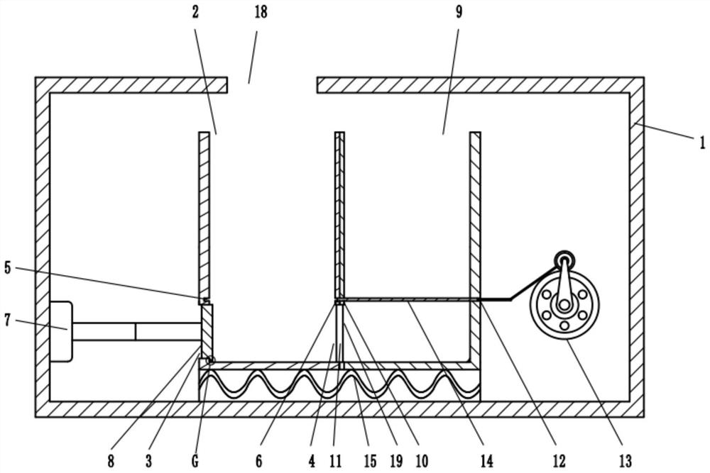
[0034] Such as figure 1 As shown, the biomass combustion furnace provided by the embodiment of the present invention includes: a combustion furnace body 1, a first furnace 2, a telescopic mechanism 7, a push plate 8, a second furnace 9, a push-pull mechanism 13, a partition 14 and a baffle 11 , The feed inlet 18 is provided on the upper end surface of the combustion furnace body 1, and the biomass fuel is fed from here. The first furnace 2 is a square tube, which is vertically arranged in the combustion furnace body 1 and has a gap with the combustion furnace body 1. There is a first through hole 3 at the lower end of the left side wall, the first through hole 3 is adjacent to the front and rear side walls of the first furnace 2, and the right side wall has a second through hole 4, the first through hole 3 corresponds to the second through hole 4 The size of the first furnace 2 is the same. The front and back and left inner walls of the first furnace 2 have a first chute 5 that communicates with each other. The right side wall of the first furnace 2 has a first communicating hole 6 that corresponds to the first chute 5 , The hole wall of the first communication hole 6 abuts against the front and rear side walls of the first furnace 2, the first chute 5 communicates with the first communication hole 6, the lower end surface of the first furnace 2 is grid-shaped, and the telescopic mechanism 7 is perpendicular to The axial direction of the burner body 1 is arranged between the burner body 1 and the first furnace 2, and it is telescopic in the horizontal direction. The fixed end is arranged on the burner body 1, the telescopic end can extend from the communicating hole 3, and the push plate 8 is vertical It is arranged to match the inner size of the communicating hole 3, and the part or all of the fixed connection with the telescopic end of the telescopic mechanism 7 is always located in the first hearth 2. The second hearth 9 is connected side by side with the first hearth 2 and is connected to the first hearth 2. The size and shape are the same, the left side wall has a third through hole 10 and a fourth through hole 19, and the third through hole 10 and the fourth through hole 19 are respectively the same in size as the positions of the first through hole 6 and the second through hole 4, The front and rear inner side walls are provided with a second slide groove, the second slide groove corresponds to the first slide groove 5, the right side wall has a second communication hole 12, the second communication hole 12 and the second slide groove are on the same horizontal plane, and the lower end surface is a net The push-pull mechanism 13 is arranged between the combustion furnace body 1 and the second furnace hearth 9, the movable end extends into or out of the second furnace hearth 9 in the horizontal direction, the fixed end is arranged in the combustion furnace body 1, and the partition plate 14 is arranged horizontally In the combustion furnace body 1, the right side end is fixedly connected to the movable end of the push-pull mechanism 13, and the front and rear side ends slide along the second chute and the first chute 5, which can close the first furnace 2 or the second furnace 9. The upper and lower end surfaces of 11 are slidingly connected with the upper and lower inner walls of the second through hole 4, and the outer end extends through the burner body 1 and out of the burner body 1, so that the second through hole 4 can be closed or opened.
[0035] Use method and working principle: The traditional biomass burning furnace has only one furnace, which is set in the burner body 1. In the present invention, two furnaces are designed. When in use, only biomass fuel is added to the first furnace 2. At this time, the baffle 11 closes the second through hole 4. When the upper layer of fuel is burned out, after adding fuel to the first furnace 2 again, the partition 14 is first moved along the second chute and the first chute through the push-pull mechanism 13 5 Slide until the left end of the partition plate 14 abuts against the first chute 5 on the left inner wall of the first furnace 2. At this time, the partition plate 14 separates the fuel in the first furnace 2 into upper fuel and lower fuel, The height of the lower fuel layer is smaller than the height of the upper fuel layer. In this embodiment, the push-pull mechanism 13 can be operated manually or electrically by other means, as long as the push-pull partition 14 can be moved horizontally, and then the baffle 11 is removed from the first furnace 2 and the second furnace 9 are pulled out. For example, a handle can be provided on the outside of the baffle 11 extending out of the burner body 1. This handle needs to be a non-conductive handle to avoid scalding the operator. Pull the handle to pull the partition 14 out At this time, the second through hole 4 is opened, and the telescopic mechanism 7 is extended to make the push plate 8 slide along the bottom wall of the first furnace 2 to push the lower unburned fuel into the second furnace 9 for combustion, and then expand and contract The mechanism 7 is shortened to reset the push plate 8 to the left side wall of the first furnace 2. The right side wall of the push plate 8 is always in the cavity of the first furnace 2 and partially closes the first through hole 3, which can ensure that no fuel Enter between the burner body 1 and the first furnace 2 through the first through hole 3, push the baffle 11 into the second through hole 4 to close it, and then pull the baffle 14 back to the second furnace by the push-pull mechanism 13 Within 2 times, repeat the above steps until the next time you add fuel
[0036] The present invention designs two furnaces. During use, only the biomass fuel is added to the first furnace, so that when the upper fuel in the first furnace is burned out, the baffle is pulled out and the partition is pushed to the first furnace. By pushing the push plate to the second furnace, the under-burned biomass fuel at the bottom of the first furnace can be fully burned in the second furnace, so that the biomass fuel can be fully utilized and the heat conversion efficiency is also improved.
[0037] In this embodiment, the telescopic mechanism 7 is a hydraulic cylinder, the telescopic end of the hydraulic cylinder is fixedly connected to the push plate 8, and the fixed end is fixed to the left inner wall of the combustion furnace body 1, or a plurality of small ports can be opened on the partition 14 The hole allows wind to enter the second furnace 9 from the small through hole of the partition 14, but the diameter of the small through hole will not allow the biomass fuel to leak through the small through hole.
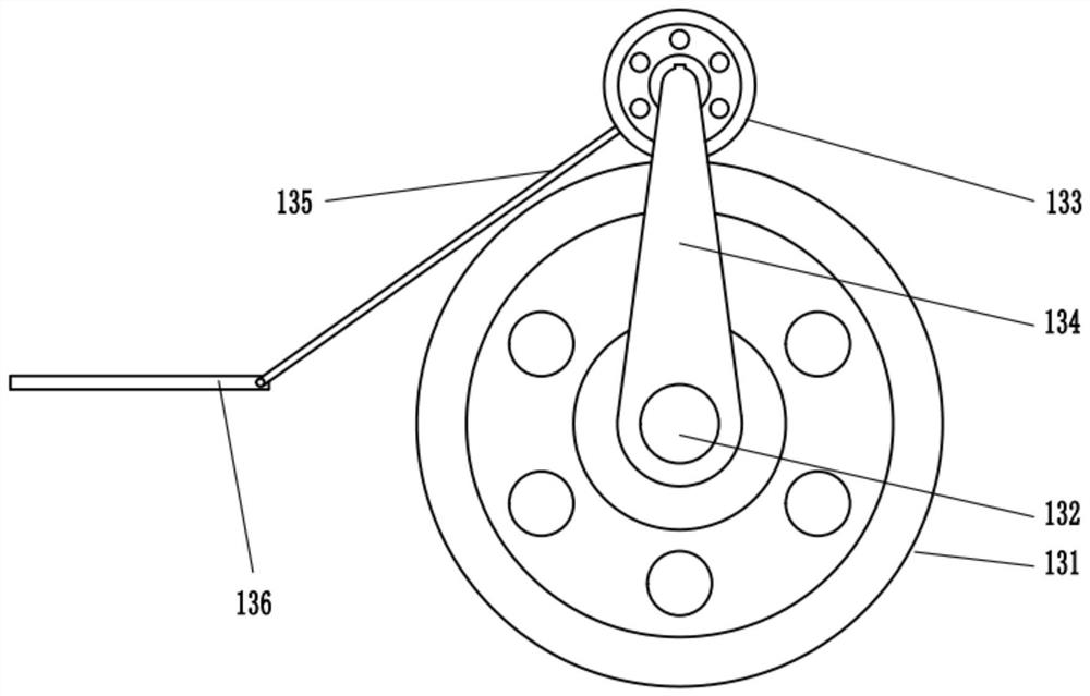
[0038] Such as figure 2 As shown, the push-pull mechanism 13 includes: driving teeth 131, driven teeth 133, connecting rods 134, push rods 135 and push blocks 136. The driving teeth 131 are hinged with the front and rear side walls of the furnace body 1 through a rotating shaft 132, and the driven teeth 133 meshes with the driving tooth 131, one end of the connecting rod 134 is fixedly connected to the shaft 132, the other end is hinged with the center of the driven tooth 133, the first end of the push rod 135 is hinged with the center of the driven tooth 133, and the push block 136 is hinged with the center of the driven tooth 133. The second end of the push rod 135 is hinged, and the left end is fixedly connected to the partition 14.
[0039] Method of use and working principle: In this embodiment, one end of the rotating shaft 132 needs to extend out of the outer side wall of the burner body 1, and the rotating handle can also be connected to the extended end. It needs to be made of heat-insulating material and is connected to the burner body 1 through a bearing. Just connect, when in use, turn the handle, the shaft 132 drives the driving tooth 131 to rotate counterclockwise, driving the driven tooth 133 meshing with it to rotate, the driven tooth 133 surrounds the outer circumference of the driving tooth 131 with the center of the driving tooth 131 as the center. During the rotation, the connecting rod 134 rotates synchronously with the driven tooth 133 during this process, which limits the driven tooth 133 so that it will not disengage from the driving tooth 131, and the push rod 135 pushes the push block 136 to reciprocate.
[0040] Specifically, the push-pull mechanism 13 also includes a power mechanism, which is provided on the combustion furnace body 1, and the output end is axially connected to the rotating shaft 132 to rotate the rotating shaft 132, which can provide power for manual operation or a motor.
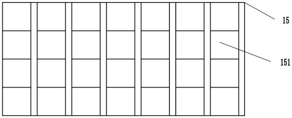
[0041] Such as image 3 As shown, the bottom of the combustion furnace body 1 is fixedly connected with a wave-shaped ventilation plate 15 which has a plurality of grids 151. The existing combustion furnace body 1 is equipped with drawers at the lower part, and the burnt fuel will It becomes powder and leaks into the drawer from the grid on the lower end of the first furnace 2 and the second furnace 9, and the drawer also plays a role of ventilation. In this embodiment, the bottom of the burner body 1 is provided with a wave shape The ventilation plate 15 can increase the air intake of the first furnace 2 and the second furnace 9, so that the bottom fuel is burned more fully, so that the biomass fuel can be fully utilized, and the heat conversion efficiency is also improved. Such as Figure 4 As shown, the lower end of the left inner wall of the first furnace 2 and the right inner wall of the second furnace 9 has an arc plate 16, and the lower end of the push plate 8 has an arc structure 17, and the arc structure 17 matches the arc plate 16. The corner position is set in an arc shape to prevent the biomass fuel from being accumulated in the dead corner position, which is not conducive to combustion, to ensure that the biomass fuel is fully utilized, and the heat conversion efficiency is also improved.
[0042] Optionally, the lower end surface of the push plate 8 is slidably connected with the inner bottom wall of the first furnace 2 to ensure that the push plate 8 will not be deflected due to fuel resistance during the pushing process, ensuring that the biomass fuel is fully utilized. At the same time, the heat conversion efficiency is improved.
[0043] The above-disclosed are only a few specific embodiments of the present invention, but the embodiments of the present invention are not limited thereto, and any changes that can be thought of by those skilled in the art should fall within the protection scope of the present invention.

PUM

no PUM

Description & Claims & Application Information

We can also present the details of the Description, Claims and Application information to help users get a comprehensive understanding of the technical details of the patent, such as background art, summary of invention, brief description of drawings, description of embodiments, and other original content. On the other hand, users can also determine the specific scope of protection of the technology through the list of claims; as well as understand the changes in the life cycle of the technology with the presentation of the patent timeline. Login to view more.

Similar technology patents

High-heat-conduction ceramic heater

InactiveCN104853459AGood thermal conductivityHigh heat conversion efficiencyHeating element materialsCorrosion resistantDiethylene glycol
Owner:QINGDAO GUOHANG XIANGYU TECH SERVICE

Portable heating type heat preservation box

PendingCN107713257AHigh heat conversion efficiencyReduce volumeTable equipmentsOther accessoriesIngested foodMaterials science
Owner:鹿寨县实验高级中学

Efficient steam generator

InactiveCN104976603ASteam pressureHigh heat conversion efficiencySteam generation heating methodsEngineeringNozzle
Owner:QINGDAO YUNLU ENERGY TECH

Non-metallic material plane heating device

Owner:KUNSHAN YALIKANG ELECTRONICS TECH CO LTD

Classification and recommendation of technical efficacy words

  • High heat conversion efficiency

Mix-driving and energy-saving device of continuously variable motor vehicle

InactiveCN101037087AHigh heat conversion efficiencyReduce idling energy consumptionGearing controlTransmission elementsElectronic control unitVariator
Owner:朱荣辉

Low-grade thermally-driven Rankine power generation device with ejector

InactiveCN102635416AIncrease workHigh heat conversion efficiencySteam engine plantsInjectorWorking fluid
Owner:ZHEJIANG UNIV

Railway rail surface laser-cladding rust-proof conducting method and apparatus for implementing method

PendingCN107386023ASmall heat affected zoneHigh heat conversion efficiencyRailway track constructionElectrical controlMetal powder
Owner:山东中科中美激光科技有限公司
Why Eureka
Try Eureka