Burner with gas combing device

A gas and burner technology, applied in the field of stoves, can solve the problems of inconsistent flame state, affecting combustion effect and combustion performance, achieve uniform and stable combustion, and suppress the effect of flameout noise

Pending Publication Date: 2020-11-20
VATTI CORP LTD
View PDF0 Cites 3 Cited by
  • Summary
  • Abstract
  • Description
  • Claims
  • Application Information

AI Technical Summary

Problems solved by technology

[0002] The combustion system of a domestic gas stove is mainly composed of a burner head and a fire cover. The gas premixed in the burner head cavity directly reaches the fire cover through the burner gas distribution channel and burns through the fire hole. The speed of the gas from the passage to each position of the fire cover is different, which will lead to inconsistent flame states during combustion, which will affect the combustion effect and combustion performance

Method used


Image

  • Burner with gas combing device
  • Burner with gas combing device
  • Burner with gas combing device

Examples


Embodiment 1

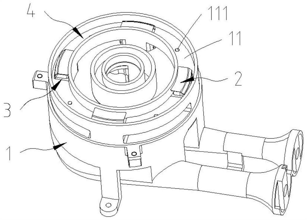
[0031] The gas flow path of the outer ring of the existing burner is: after the gas flows out from the gas channel of the burner head, it is generally divided into two parts, one part directly flows upward into the cavity of the fire cover, and the other part flows to the left and right sides of the gas channel outlet of the burner head. side flow. First gradually fill the outer ring air chamber of the burner and then overflow to the cavity of the fire cover, and the gas in the cavity of the fire cover flows out from the fire hole of the fire cover and burns. Because the gas flow rate directly upwards from the gas channel of the burner head is greater than the gas flow rate from the outer ring air cavity of the burner head, the gas flow rate flowing into each position of the fire cover cavity is different. When the existing burner executes the flameout operation, the gas flow rate of the gas channel of the burner drops suddenly. After the gas in the corresponding local fire co...

Embodiment 2

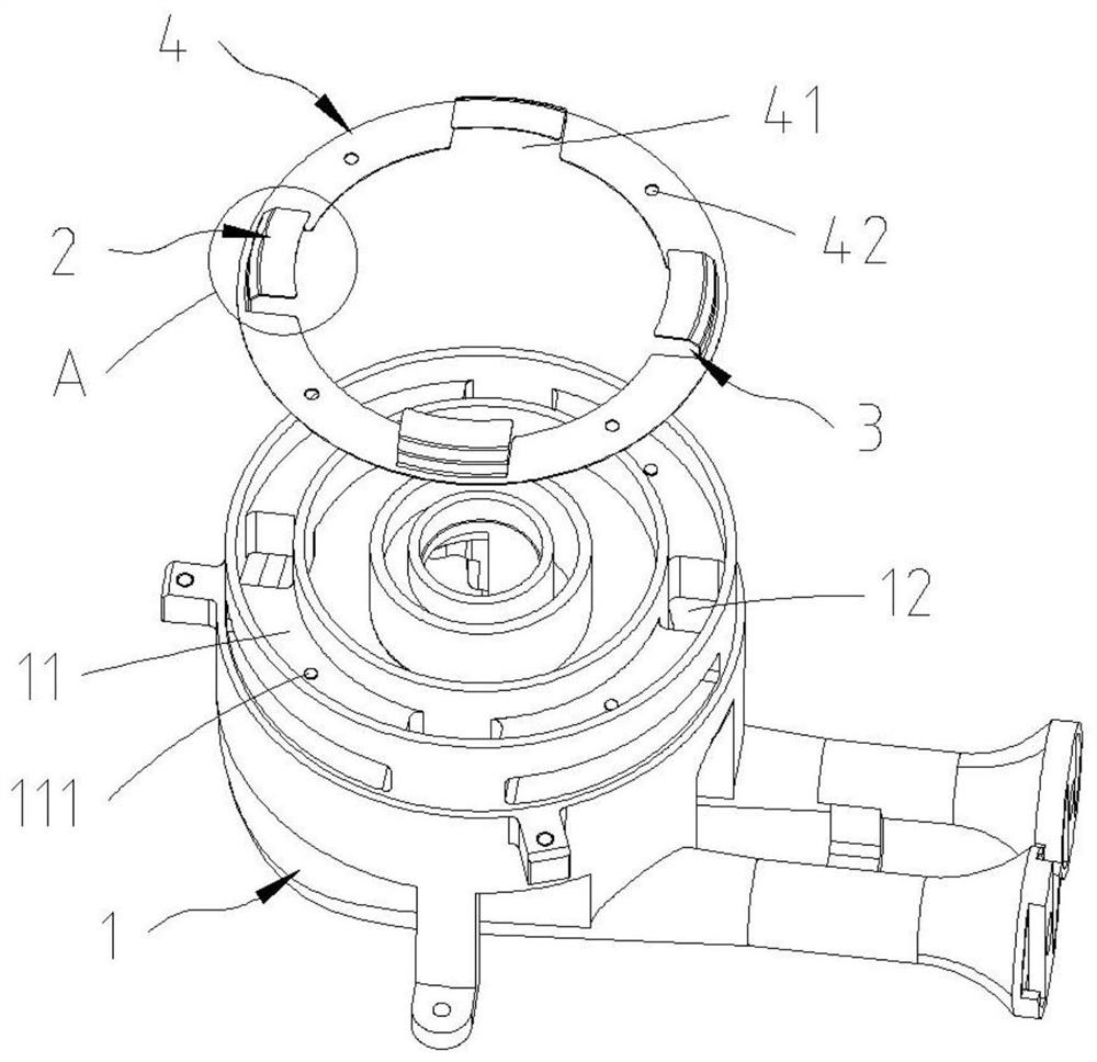
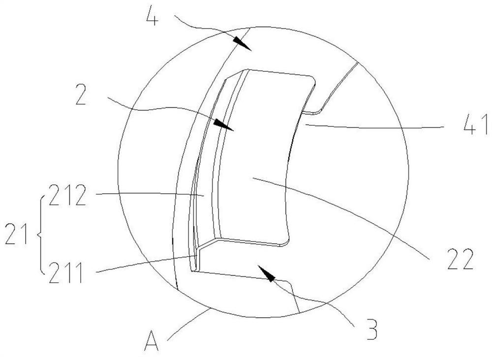
[0047] Such as Figure 4 As shown, the difference between this embodiment and embodiment 1 lies in the structure of the barrier structure 2 . Specifically, the blocking structure 2 is a baffle (not shown in the figure) arranged obliquely in the vertical direction, the baffle is arranged above the opening of the annular support 4, and the lower side of the baffle is connected to the annular support 4 , and abut against the outer ring wall of the air mixing chamber through the outer side of the annular support 4 . The upper side of the deflector extends obliquely upwards to and abuts against or connects to the inner ring wall of the gas mixing chamber, so that the deflector, the bottom of the gas mixing chamber and the inner ring wall jointly define a combing channel with left and right air outlets .

[0048] In this embodiment, the deflector is an arc surface, and the deflector is formed by partially cutting and stamping the annular support 4 and then turning upwards, and the...

Embodiment 3

[0051] Such as Figure 5 As shown, the difference from Embodiment 1 is that the gas combing device of this embodiment omits the annular support. Specifically, an installation groove 13 is provided on the outer ring wall of the gas mixing chamber 11 corresponding to the outlet of the gas channel. The blocking structure 2 is in the shape of a "7", and the outer lower end surface is provided with an outwardly extending installation part 203. During installation, The installation portion 203 of the blocking structure 2 is inserted into the installation groove 13 , and the inner side abuts against the inner ring wall of the air mixing chamber 11 facing the installation groove 13 .

[0052] It can be seen that by omitting the annular support and inserting the mounting part 203 of the blocking structure 2 into the mounting groove 13, the inner side of the blocking structure 2 abuts against the inner ring wall of the gas mixing chamber 11, not only realizing the stabilization of the b...


PUM


Abstract

The invention discloses a burner with a gas combing device. The burner comprises a burner body and the gas combing device. The burner body is provided with a gas mixing cavity and at least two gas channels. The gas combing device comprises a blocking structure arranged in the gas mixing cavity and located above gas channel outlets. The blocking structure is provided with a gas combing channel communicating with the gas channels, or the blocking structure, the bottom and surrounding wall of the gas mixing cavity jointly define the gas combing channel communicating with the gas channels. The left side and/or right side of the gas combing channel are/is provided with gas outlets/a gas outlet communicating with the gas mixing cavity. The burner is provided with the blocking structure, thus when gas flow flows into the gas mixing cavity, the flow speed is lowered, the flow direction is changed, the flow direction and flow speed of the gas flowing into the gas mixing cavity are combed, burning is more uniform and stable, and meanwhile flameout noise can be effectively restrained.

Description

technical field [0001] The invention relates to the technical field of cookers, in particular to a burner head used for cookers. Background technique [0002] The combustion system of a domestic gas stove is mainly composed of a burner head and a fire cover. The gas premixed in the burner head cavity directly reaches the fire cover through the burner gas distribution channel and burns through the fire hole. The speed of the gas from the channel to each position of the fire cover is different, which will lead to inconsistent flame states during combustion, which will affect the combustion effect and combustion performance. [0003] In addition, when the burner performs the flameout operation, especially the outer fire cover, it is generally not that the entire outer fire cover is turned off at the same time, but the flame is partially turned off first, and then all the flames are turned off due to the complete cut-off of the gas in a short period of time. After the outer fir...

Claims


Application Information

Patent Timeline
Patent Type & Authority Applications(China)
IPC IPC(8): F24C3/08F23D14/02F23D14/46F23D14/62F23D14/60F23D14/68
CPCF23D14/02F23D14/46F23D14/60F23D14/62F23D14/68F24C3/085
Inventor 刘华荣卢华枝潘叶江
Owner VATTI CORP LTD
Why Eureka
Try Eureka