A medical syringe detection device
A detection device and syringe technology, applied in the direction of measuring device, machine/structural component testing, instruments, etc., can solve the problems of non-standard pulling action, easy shaking of the syringe, inaccurate parameters, etc., to achieve reliable fixation and improve detection work. Speed, anti-shake effect
- Summary
- Abstract
- Description
- Claims
- Application Information
AI Technical Summary
Problems solved by technology
Method used
Image
Examples
Embodiment 1
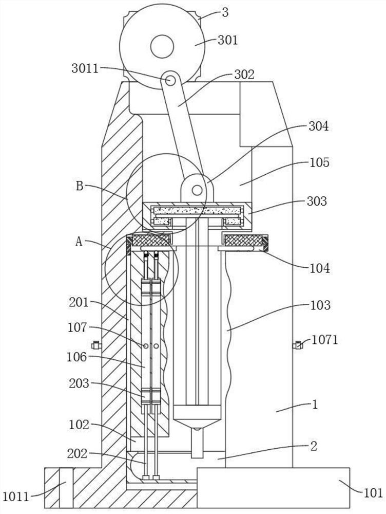
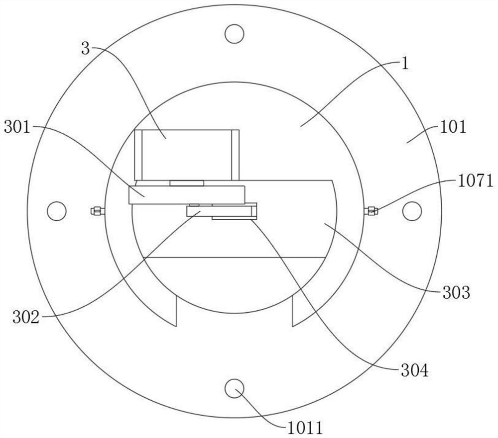
[0028] refer to Figure 1-4 , a medical syringe detection device, including a base 1 and a drive motor 3 fixedly connected to the top of the base 1, the base 1 is sequentially provided with a first sliding cavity 102, a through groove 103, a positioning cavity 104 and a second Two sliding chambers 105, the first sliding chamber 102 is slidably connected with the liquid storage box 2, the top of the positioning chamber 104 is rotatably connected with the driving wheel 4, the bottom of the positioning chamber 104 is rotatably connected with the ball 504, and the second sliding chamber 105 is slidably connected with the card Disk 303, a clamping cavity 3033 is opened in the chuck 303, and the clamping cavity 3033 is connected with the first clamping roller 3031 and the second clamping roller 3032 in sequence from top to bottom, and the top of the chuck 303 is fixedly connected with a rotating seat 304 , the output end of the drive motor 3 is fixedly connected to the turntable 301...
Embodiment 2
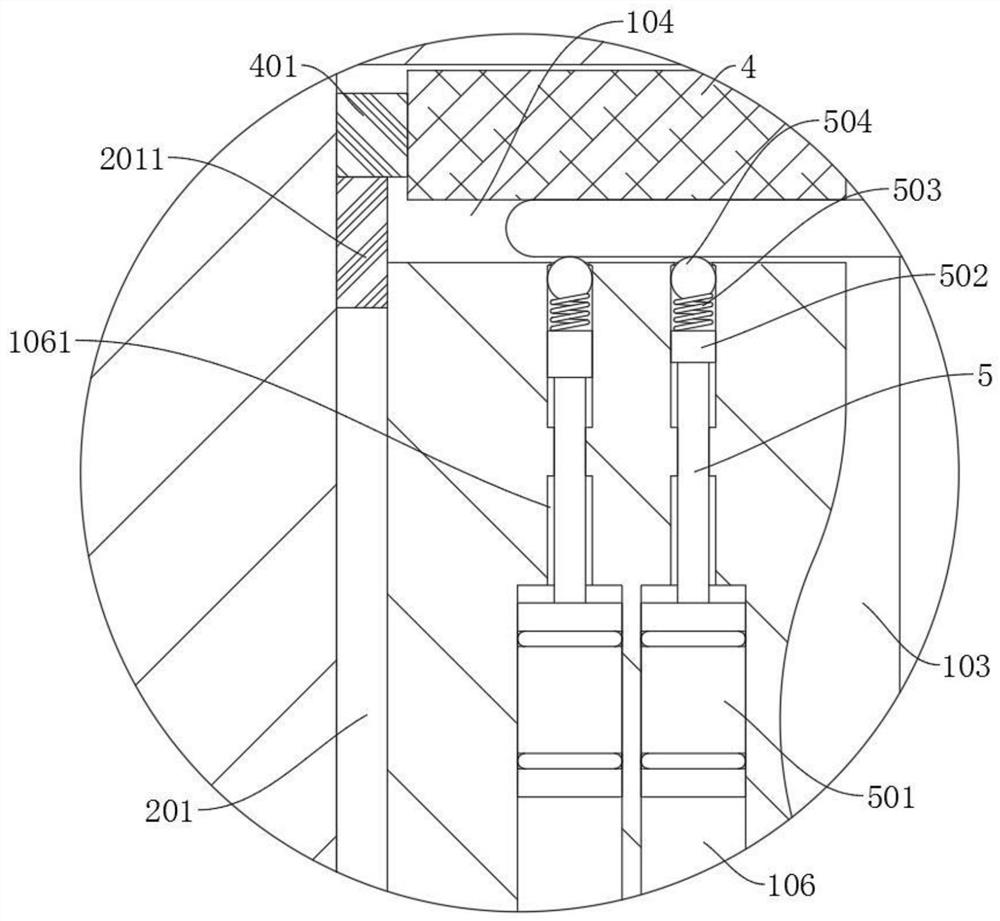
[0031] refer to figure 1 and image 3, which is basically the same as that of Embodiment 1, furthermore, an air storage cavity 106 is opened in the base 1, an exhaust pipe 107 is provided on the air storage cavity 106, and a valve 1071 is provided on the exhaust pipe 107 extending to the outside of the base 1 , the liquid storage box 2 is fixedly connected with the second telescopic rod 202, the top of the second telescopic rod 202 is fixedly connected with the second piston 203, the second piston 203 is slidably connected with the bottom of the gas storage chamber 106, and the top of the gas storage chamber 106 has a limited position Cavity 1061, the limit chamber 1061 is slidingly connected with the first telescopic rod 5, and the two ends of the first telescopic rod 5 are respectively fixedly connected with the top block 502 and the first piston 501, and the first piston 501 is slidably connected in the air storage chamber 106 , the top of the limiting cavity 1061 communic...
Embodiment 3
[0034] refer to Figure 1-2 and Figure 4 , which is basically the same as that of Embodiment 1, and furthermore, the material of the first pinch roller 3031 and the second pinch roller 3032 is rubber, and the bottom of the base 1 is fixedly connected with a positioning plate 101, and the positioning plate 101 is uniform in circumference. There are positioning holes 1011. During use, the clamping roller made of rubber has partial deformation ability, which can not only effectively clamp the piston handle of the syringe, but also facilitate access. Before use, fix the positioning plate 101 on the On the workbench, prevent shaking during detection and improve the accuracy of detection data.
PUM
 Abstract
Description
Claims
Application Information
 - R&D
- Intellectual Property
- Life Sciences
- Materials
- Tech Scout
- Unparalleled Data Quality
- Higher Quality Content
- 60% Fewer Hallucinations
Browse by: Latest US Patents, China's latest patents, Technical Efficacy Thesaurus, Application Domain, Technology Topic, Popular Technical Reports.
© 2025 PatSnap. All rights reserved.Legal|Privacy policy|Modern Slavery Act Transparency Statement|Sitemap|About US| Contact US: help@patsnap.com


