Eureka AIR delivers breakthrough ideas for toughest innovation challenges, trusted by R&D personnel around the world.

Solar panel packaging equipment

A technology for solar panels and packaging equipment, applied in photovoltaic power generation, electrical components, climate sustainability, etc., can solve problems such as low efficiency, uneven width of side seams, and poor packaging quality

Active Publication Date: 2020-11-20
瞿磊
View PDF4 Cites 1 Cited by
  • Summary
  • Abstract
  • Description
  • Claims
  • Application Information

AI Technical Summary

Problems solved by technology

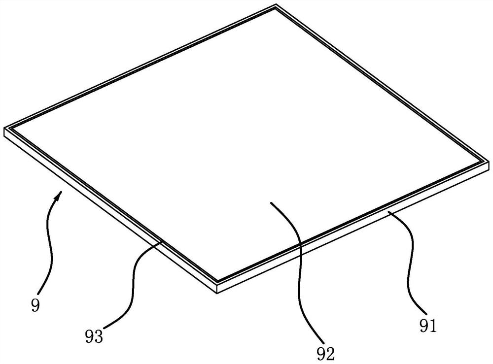
The main functional part of the solar panel is the core board, which needs to be fixed in the outer frame during the processing, such as figure 1 As shown, the solar panel 9 includes an outer frame 91 and a core plate 92, the outer frame 91 is rectangular, the core plate 92 is arranged in the outer frame 91, and a side seam 93 will be generated between the outer edge of the core plate 92 and the inner edge of the outer frame 91 , the side seam 93 is used to fill the sealant for packaging, which plays the role of sealing protection and fixing the core board 92. The filling of the existing sealant is usually performed manually with a glue gun, which is prone to uneven width of the side seam, resulting in poor packaging quality. poorer and less efficient

Method used


Image

  • Solar panel packaging equipment
  • Solar panel packaging equipment
  • Solar panel packaging equipment

Examples


Embodiment Construction

[0038] The following are specific embodiments of the present invention and in conjunction with the accompanying drawings, the technical solutions of the present invention are further described, but the present invention is not limited to these embodiments.

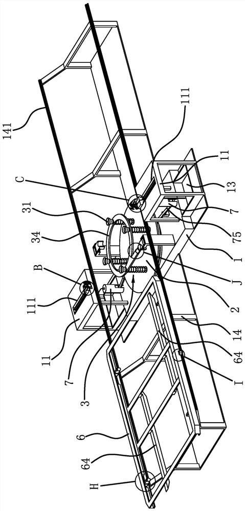
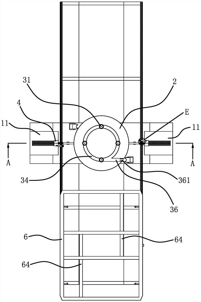
[0039] Such as figure 2 , image 3 , Figure 4 , Figure 5 As shown, a solar panel packaging device includes a base 1 and a turntable 2 that is horizontally arranged and rotatably connected to the base 1. A number of positioning columns 3 are vertically connected to the turntable 2, and the tops of the plurality of positioning columns 3 are provided with a The suction cup 31 for the horizontal adsorption and positioning of the solar panel 9 is provided with a feeding mechanism capable of horizontally transporting the solar panel 9 to the top of the positioning column 3 on one side of the turntable 2, and the base 1 is horizontally fixed with support plates 11 on both sides of the turntable 2 , the support plate 11 is s...


PUM


Abstract

The invention provides solar panel packaging equipment, and belongs to the technical field of new energy equipment. The problem that an existing solar panel is poor in packaging quality is solved. Thesolar panel packaging equipment comprises a base and a turntable, and the turntable is vertically connected with a plurality of positioning columns; suckers are arranged at the top ends of the positioning columns; a feeding mechanism is arranged on one side of the turntable; supporting plates are horizontally fixed to the positions, on the two sides of the turntable, of the base. A sliding base is slidably connected to the supporting plate. The two sliding seats are rotationally connected with guide wheels; a tensioning spring is further arranged between the sliding base and the supporting plate, a rotating column is rotationally connected to the sliding base, a distance fixing disc is rotationally connected to the upper end of the rotating column, a guide plate is vertically and fixedlyconnected to the lower end of the rotating column and is parallel to the distance fixing disc, a sealant injection pipe is further arranged on the sliding base, and a sealant feeding mechanism capableof quantitatively conveying sealant to the sealant injection pipe is arranged on the base. According to the solar panel packaging equipment, glue filling packaging can be carried out on the edge seams of the solar panel, and the packaging quality is improved.

Description

technical field [0001] The invention belongs to the technical field of new energy equipment, and relates to a solar panel packaging equipment. Background technique [0002] A solar cell, also known as a solar chip or a photovoltaic cell, is a photoelectric semiconductor sheet that uses sunlight to generate electricity directly. It belongs to new energy equipment. A single solar cell cannot be directly used as a power source. As a power source, several single solar cells must be connected in series or in parallel. Connected and tightly packaged into components, including solar panels, also called solar cell components, are the core part of the solar power generation system and the most important part of the solar power generation system. The main functional part of the solar panel is the core board, which needs to be fixed in the outer frame during the processing, such as figure 1 As shown, the solar panel 9 includes an outer frame 91 and a core plate 92, the outer frame 91 ...

Claims


Application Information

Patent Timeline
IPC IPC(8): H01L31/18H01L31/048H01L21/67
CPCH01L21/67121H01L31/048H01L31/18Y02E10/50Y02P70/50
Inventor 瞿磊
Owner 瞿磊
Why Eureka
Eureka Blog
Learn More