Non-perception user load interactive adjustment system
A system-adjusted, non-sensing technology, applied in AC network load balancing, cooling/ventilation/heating renovation, electrical components, etc., which can solve problems such as insufficient power grid power load adjustment and inability to adjust user power load in advance. , to achieve the effect of improving the power consumption experience, improving the service life and simple installation
- Summary
- Abstract
- Description
- Claims
- Application Information
AI Technical Summary
Problems solved by technology
Method used
Image
Examples
Embodiment 1
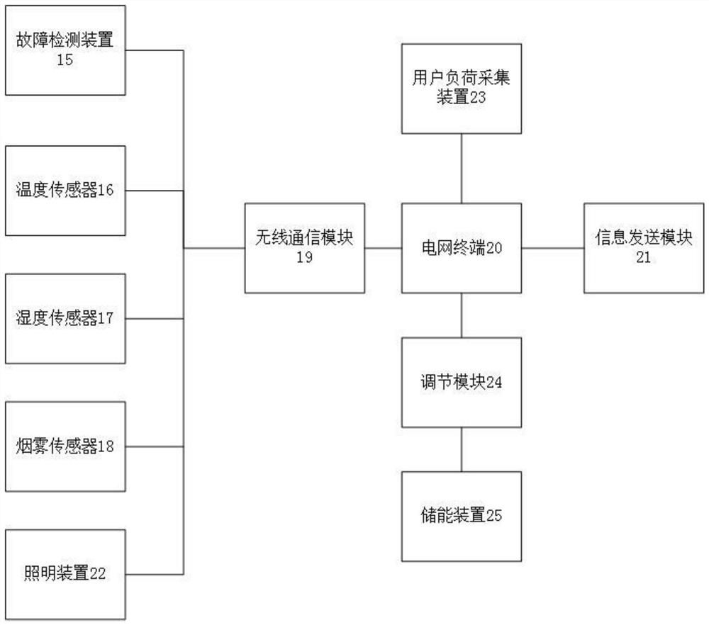
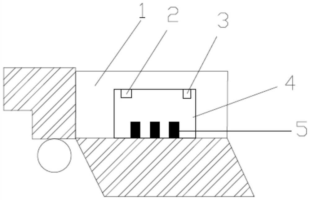
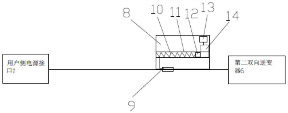
[0024] Embodiment 1: A non-perceptual user load interactive adjustment system, such as figure 1 As shown, it includes a user load collection device 23, a grid terminal, an adjustment module 24 and an energy storage device 25; the user load collection device 23 is installed on the line on the side of the user's electric meter, and is used to collect the user's power load and connect to the grid terminal; The grid terminal is used to control the adjustment module 24 to adjust the power delivered to the user according to the size of the user's electricity load; the adjustment module 24 controls the energy storage device 25 to perform energy storage on the grid side or discharge on the user side according to the received instructions; the energy storage device 25 mobile device 1, energy storage box, fire protection system, information sending module 21, heating device and heat dissipation device, the energy storage box is installed on the mobile device 1, and the fire protection sy...
Embodiment 2
[0030] Embodiment 2, a non-perceptual user load interactive adjustment system. Compared with Embodiment 1, the difference between this embodiment is that the monitoring system 3 also includes a lighting device 22 and a camera. Both the camera and the lighting device 22 communicate with each other through the wireless communication module 19. The grid terminal 20 is connected, and the lighting device 22 includes a track, a motor, a pulley, a pole, a power supply device and an LED lamp. The track is installed on the inner wall of the box body 4, and the motor is installed on one side of the track. Connect to the grid terminal 20, the output end of the motor is connected to the pulley, the pulley matches the track, the pole is installed on the pulley, the power supply device is installed on one side of the pole, the LED lamp is installed on the pole, the LED lamp and the power supply device connect.
Embodiment 3
[0031] Embodiment 3, a non-aware user load interactive adjustment system, such as Figure 4 As shown, the present embodiment differs from the first embodiment in that the user load collection device 23 includes a base 26, a second current transformer 27, a second spring 28, a second slider 33, a second pressure sensor 32, a second Three pressure sensors 31 and a controller 30, the substrate 26 is installed on the line on the user's ammeter side, the second current transformer 27 is used to collect the current of the user's ammeter side line, the output end of the current transformer is connected with the second spring 28, the second One end of the second spring 28 is fixedly connected with the inner wall of the base body 26, and the other end of the second spring 28 is connected with the second slider 33. The base body 26 is provided with a second chute 29, and the second pressure sensor 32 and the third pressure sensor 31 are both Fixedly installed in the second sliding groov...
PUM
 Abstract
Description
Claims
Application Information
 - R&D
- Intellectual Property
- Life Sciences
- Materials
- Tech Scout
- Unparalleled Data Quality
- Higher Quality Content
- 60% Fewer Hallucinations
Browse by: Latest US Patents, China's latest patents, Technical Efficacy Thesaurus, Application Domain, Technology Topic, Popular Technical Reports.
© 2025 PatSnap. All rights reserved.Legal|Privacy policy|Modern Slavery Act Transparency Statement|Sitemap|About US| Contact US: help@patsnap.com


