Stabilising rod for orthopaedic aid

An orthopedic, stabilizer rod technology, applied in non-surgical orthopedic surgery, medical science, foot bandages, etc., can solve problems such as damage to the fabric, and achieve the effect of omitting the lamination step

Active Publication Date: 2020-11-20
BAUERFEIND GMBH & CO
View PDF19 Cites 0 Cited by
  • Summary
  • Abstract
  • Description
  • Claims
  • Application Information

AI Technical Summary

Problems solved by technology

Also, metal may damage the fabric against which it is attached

Method used


Image

  • Stabilising rod for orthopaedic aid
  • Stabilising rod for orthopaedic aid
  • Stabilising rod for orthopaedic aid

Examples


Embodiment Construction

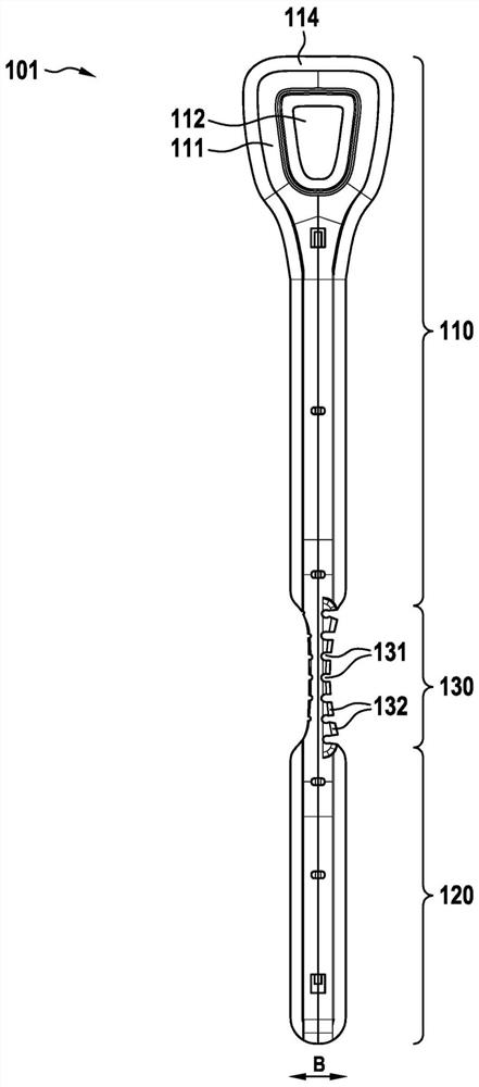
[0059] figure 1 A stabilizer bar 101 according to the invention is shown. The stabilizer bar 101 is designed in one piece and molded from plastic. According to the present invention, the stabilizer bar 101 is divided into a first part 110, a second part 120 and a third part 130, and the third part connects the first part 110 and the second part 120 to each other. The third portion 130 is tapered in width B compared to the first and second portions 110 , 120 and also has seven material notches 131 . In this case, the deeper the material recess 131 is, the further it is from the middle region of the flexible third part 130 . Thus, the flexibility of the third portion 130 of the stabilizer bar 101 is greater than the flexibility of the first portion 110 and the second portion 120 . In particular, a bending of the third part 130 in the direction of the recesses 131 is provided here, so that the tooth-shaped material projections 132 located between the recesses 131 collide with ...


PUM


Abstract

The invention relates to a stabilising rod (10) for an orthopaedic aid, the stabilising rod (101) having in the longitudinal direction a first section (110) and a second section (120), the first section (110) and the second section (120) being connected to each other via a third, flexible section (130). According to the invention, the third, flexible section (130) has at least one material cut-out(131).

Description

technical field [0001] The invention relates to a stabilizing bar for an orthopedic aid, in particular a knee bandage, and an orthopedic aid comprising at least one stabilizing bar according to the invention. Background technique [0002] The use of stabilizer bars in orthopedic aids is known. From the patent documents WO2011 / 035885A1 and DE3637879A1 a knee joint bandage with a lateral stabilizer bar is known, referred to simply as a knee bandage. Stabilizer bars made of metal are used here, which are flexible due to their design as a spring bar, ie as a full turn of a flattened helical spring. However, since such stabilizing bars are usually welded to the fabric of the orthopedic aid, at least part of the metal spring strap bar must be laminated with weldable plastic. Additionally, metal may damage the fabric against which it is attached. For this purpose, the flat helical springs used must have the same elasticity over the entire length of the spring and the degree of b...

Claims


Application Information

Patent Timeline
Patent Type & Authority Applications(China)
IPC IPC(8): A61F5/01
CPCA61F5/0102A61F2005/0179A61F5/0106A61F5/0109A61F13/061A61F2005/0169
Inventor 汉斯·B·鲍尔法因德
Owner BAUERFEIND GMBH & CO
Why Eureka
Try Eureka