Chin implant with split embedded structure

A technology for implants and chins, applied in bone implants, prostheses, medical science, etc., can solve the problems of vascular injury, poor application effect and difficult operation of mandibular gingiva, so as to reduce damage and make application Good effect, good anti-skid effect

Pending Publication Date: 2020-11-24
GHANGZHOU WANHE MATERIAL
View PDF2 Cites 0 Cited by
  • Summary
  • Abstract
  • Description
  • Claims
  • Application Information

AI Technical Summary

Problems solved by technology

[0005] The chin implant in the prior art is a whole, the implantation process is very difficult to operate, and the incision required is large, and the blood vessels below the incision must be cut off, which is likely to cause greater damage to the blood vessels of the mandibular gingiva;
[0006] In addition, the chin implants in the prior art also have the phenomenon of warping or hollowing in the middle caused by poor application effect

Method used


Image

  • Chin implant with split embedded structure
  • Chin implant with split embedded structure
  • Chin implant with split embedded structure

Examples


Embodiment 1

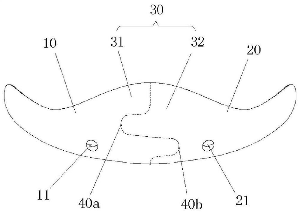
[0041] A chin implant with split fitting structure, such as figure 1 -5, it includes a left prosthesis part 10, a right prosthesis part 20, a docking part 30 used to connect the left prosthesis part 10 and the right prosthesis part 20, wherein the docking part 30 includes a first docking part 31 and a second docking part 31 Docking part 32, the first butt joint part 31 is formed on the right side of left prosthesis part 10, and the second butt joint part 32 is formed on the left side of right prosthesis part 20, between the first butt joint part 31 and the second butt joint part 32 mutually Fitting connects the left prosthetic part 10 and the right prosthetic part 20 as a whole.

[0042] See you again figure 1 , the first butt joint part 31 and the second butt joint part 32 are connected by the upper and lower two sets of fitting structures 40a, 40b to carry out opposite clamping fit connection, and the fitting structure 40a located in the upper set is taken as an example to ...

Embodiment 2

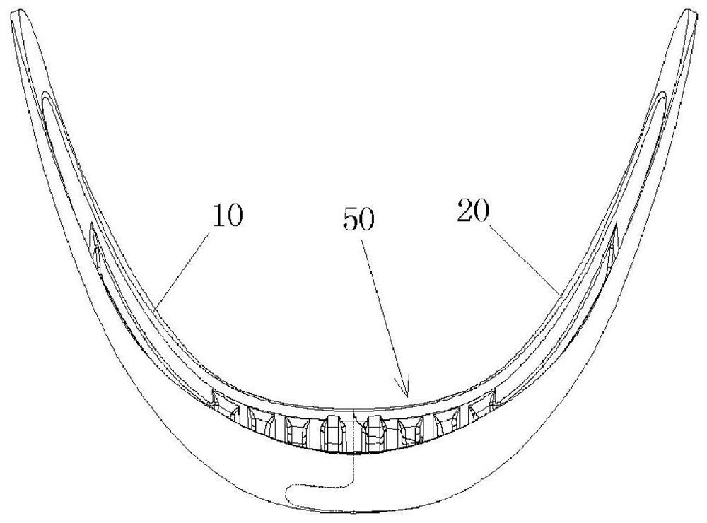
[0052] A chin implant with split fitting structure, such as Figure 6 As shown in -9, the difference between this embodiment and Embodiment 1 lies in that the arrangement of the anti-slip attachment structure 50 is different.

[0053] In this embodiment, an anti-slip attachment structure 50 is provided on the inner and outer surfaces of the chin implant and the human chin tissue, and the chin implant is closely connected to the human tissue through the anti-slip attachment structure 50. fit.

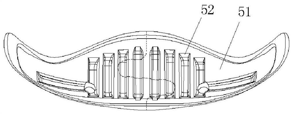
[0054] The anti-slip attachment structure 50 in this embodiment includes a depression to form an attachment groove 51 that matches the shape of the main body of the chin implant. In the attachment groove 51, there are several sand grains 53 used for anti-skid, wherein some sand grains 53 at least partially occupy the attaching groove 51 in a manner of being arranged uniformly or in pieces or oppositely.

[0055] Further, the height of some sand bodies 53 does not exceed the groove dept...


PUM


Abstract

The invention provides a chin implant with a split embedded structure. The chin implant comprises a left prosthesis part, a right prosthesis part and a butt joint part, wherein the butt joint part comprises a first butt joint part formed on the right side of the left prosthesis part and a second butt joint part formed on the left side of the right prosthesis part, and the first butt joint part andthe second butt joint part are mutually embedded to connect the left prosthesis part and the right prosthesis part into a whole. According to the invention, implantation difficulty is reduced, and anincision is small, so great damage to blood vessels of mandibular gingiva is weakened.

Description

technical field [0001] The invention relates to a chin implant with a split fitting structure. Background technique [0002] At present, the main methods of mandibular plastic surgery are prosthesis implantation and injection. Among them, the prosthesis implantation method is to implant a mandibular prosthesis (chin implant) made of silicone rubber or expanded polytetrafluoroethylene into the mandible of the beautician to repair the shape of the beautifier's jaw. , to achieve the beauty effect of making the beautician's chin plump and coordinated with the face. The shape of the chin implant can be customized according to the plastic surgeon's facial proportions and jaw shape. [0003] Chinese patent document CN201759700U discloses a mandibular prosthesis. The mandibular prosthesis is arc-shaped and includes a reinforced expanded polytetrafluoroethylene layer, and several soft layers arranged outside the reinforced expanded polytetrafluoroethylene layer. Type expanded poly...

Claims


Application Information

Patent Timeline
Patent Type & Authority Applications(China)
IPC IPC(8): A61F2/28
CPCA61F2/2875A61F2/30767A61F2002/30131A61F2002/30331A61F2002/3082A61F2002/30841A61F2002/30891
Inventor 张建军
Owner GHANGZHOU WANHE MATERIAL
Why Eureka
Try Eureka