Waste gas purification pipeline for garbage treatment

A technology for waste gas purification and garbage treatment, which is applied in chemical instruments and methods, the use of liquid separation agents, and the separation of dispersed particles. Avoid wasteful effects

Inactive Publication Date: 2020-11-24
刘雨田
View PDF7 Cites 2 Cited by
  • Summary
  • Abstract
  • Description
  • Claims
  • Application Information

AI Technical Summary

Problems solved by technology

[0003] When garbage is incinerated, a large amount of flue gas will be produced. At present, these flue gases are generally treated by atomizing sprayers, and then the treated waste gas is discharged into the atmosphere, but after the waste gas is discharged into the atmosphere, it will carry Part of the exhaust gas that has not been purified thoroughly will cause air pollution, and during the exhaust gas discharge process, the dust contained in the exhaust gas will adhere to the inner wall of the pipe, which will cause the pipe to be blocked and make exhaust difficult.

Method used


Image

  • Waste gas purification pipeline for garbage treatment
  • Waste gas purification pipeline for garbage treatment
  • Waste gas purification pipeline for garbage treatment

Examples


Embodiment 1

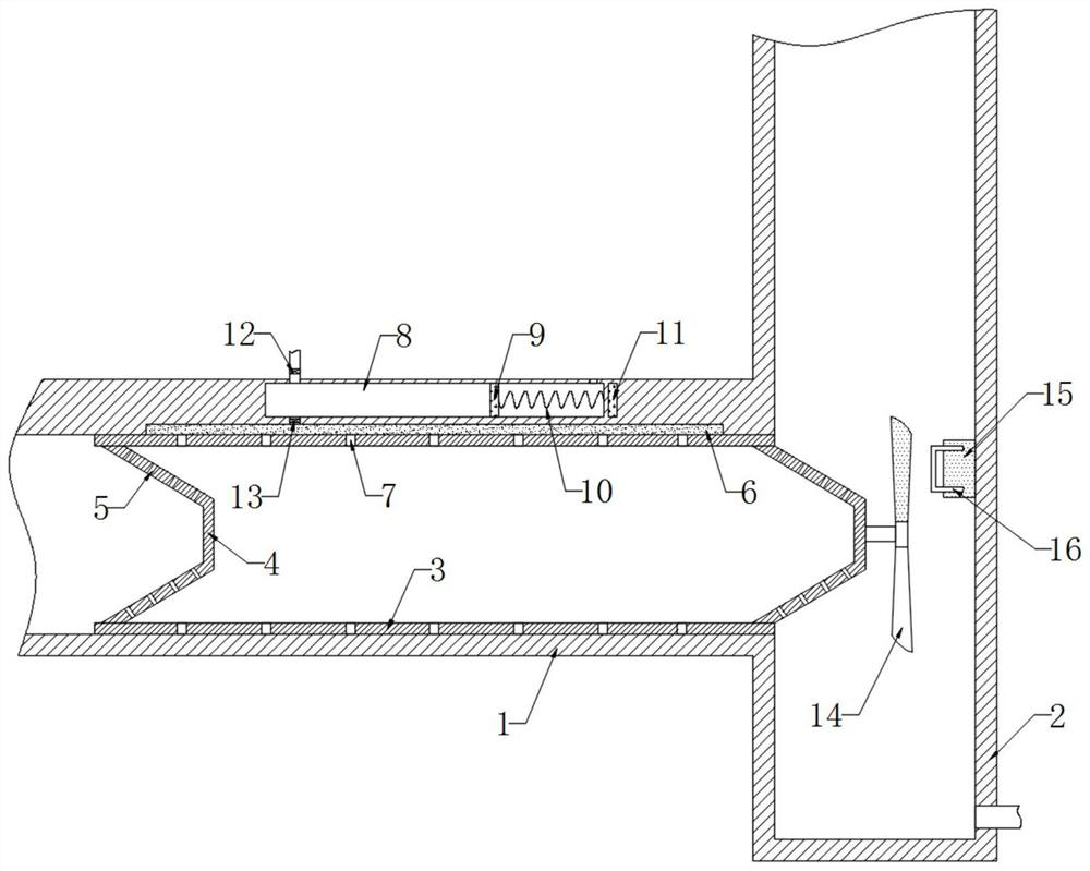
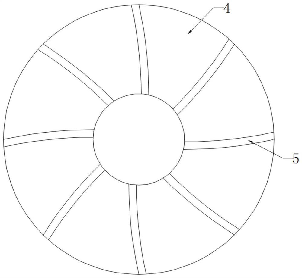
[0022] refer to Figure 1-2 , a waste gas purification pipeline for waste disposal, comprising a pipe body 1, the side wall of the pipe body 1 is fixedly connected with an exhaust pipe 2, the inner wall of the pipe body 1 is rotatably connected with a ring 3, and the inner wall of the ring 3 is symmetrically fixedly connected with a tapered pipe 4. The conical tube 4 is arranged in a hollow conical shape, and the side wall of the conical tube 4 is provided with a plurality of exhaust channels 5 uniformly distributed in the circumferential direction. Further, the plurality of exhaust channels 5 are curved and have the same direction of rotation. When When the exhaust gas flows in the pipe body, the rotational force generated by the gas flowing in the exhaust channel 5 is superimposed on each other, so that the conical pipe 4 rotates under the action of the air flow. The upper end of the pipe body 1 is embedded with a liquid absorbent cotton 6, and the inner wall of the ring 3 A...

Embodiment 2

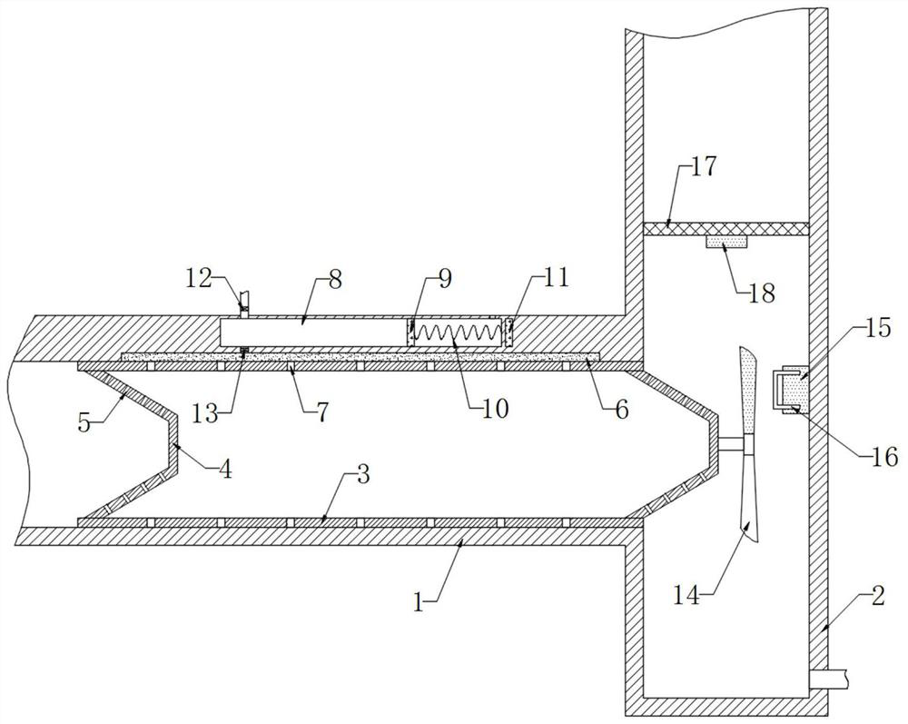
[0029] refer to image 3 , different from the first embodiment, the inner wall of the exhaust pipe 2 is fixedly connected with an elastic filter 17, and the lower end of the elastic filter 17 is fixedly connected with an iron block 18.

[0030] In this embodiment, when the air bubbles absorb harmful gas and dust and flow out from the exhaust duct 5 into the exhaust pipe 2, part of the air bubbles will flow upward in the exhaust pipe 2 along with the flow of the exhaust gas. When in contact, the air bubbles burst, and then the elastic filter 17 blocks the air bubbles to prevent the air bubbles from escaping into the air and causing secondary pollution. The net 17 shakes continuously to shake off the dust and water droplets accumulated on the elastic filter screen 17, so that the elastic filter screen 17 maintains good gas circulation and will not affect the discharge of exhaust gas.


PUM


Abstract

The invention discloses a waste gas purification pipeline for garbage treatment, including a pipe body, the side wall of the pipe body is fixedly connected with an exhaust pipe; the inner wall of thepipe body is rotationally connected with a circular ring; conical pipes are symmetrically and fixedly connected to the inner wall of the circular ring; each conical pipe is arranged in a hollow circular truncated cone shape; the side wall of each conical pipe is provided with a plurality of exhaust channels evenly distributed in the circumferential direction; liquid absorption cotton is embedded in the upper end of the pipe body; a plurality of capillary holes are formed in the inner wall of the circular ring; a sliding plug cavity is formed in the upper end of the pipe body; the inner wall ofthe sliding plug cavity is in sealed sliding connection with a magnetic sliding plug; and the side wall of the magnetic sliding plug is fixedly connected with the sliding plug cavity through a spring. When airflow flows in the pipe body at a high speed, pressure difference is generated between the two sides of the capillary holes; and then purification liquid in the capillary holes flows out towards the inner wall of the circular ring in a bubble form under the action of pressure difference, so that the contact area of the purification liquid with harmful gas and dust in the waste gas is increased, the purification efficiency of the waste gas is improved, and the consumption of the purification liquid is reduced.

Description

technical field [0001] The invention relates to the technical field of garbage treatment, in particular to a waste gas purification pipeline for garbage treatment. Background technique [0002] Garbage is the waste in people's daily life. Due to the diversity and pollution of garbage, it is necessary to carry out appropriate and harmless treatment of garbage. The current treatment methods include sanitary landfill, high-temperature composting and incineration. [0003] When garbage is incinerated, a large amount of flue gas will be produced. At present, these flue gases are generally treated by atomizing sprayers, and then the treated waste gas is discharged into the atmosphere, but after the waste gas is discharged into the atmosphere, it will carry Part of the exhaust gas that has not been purified thoroughly will cause air pollution, and during the exhaust gas discharge process, the dust contained in the exhaust gas will adhere to the inner wall of the pipe, which will ca...

Claims


Application Information

Patent Timeline
Patent Type & Authority Applications(China)
IPC IPC(8): B01D47/02B01D53/18
CPCB01D47/02B01D53/18
Inventor 刘雨田
Owner 刘雨田
Why Eureka
Try Eureka